Introduction
Support Michael Baddeley on his patreon page for files here: https://www.patreon.com/mrbaddeley/
If you wish to support the author of this guide, feel free to donate to me via paypal at http://paypal.me/guanu/
-
-
Here we will attach the magnets to the frame and side panels. You will use 4 magnets that are 5mm x 5mm cylinder and 4 magnets that are 10mm diameter x 2.5mm thick
-
Mix some epoxy and put a small amount in the holes on the frame and the holes in the side panels.
-
First insert the magnets in the frame. Then get the matching side panel for that frame and 2 of the 10mm magnets for the side panel. Make sure the side of the magnet that attracts to the magnet in the frame is the side you see when you put them in the side panel.
-
Do the same to the other side of the frame and other side panel. Doing it this way makes sure the side panel magnets attract to the magnets in the frame rather than repel each other.
-
-
-
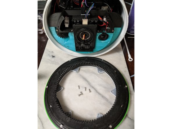
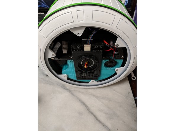
Here we will use 5 M3 x 10mm long countersunk screws to attach one of the lazy susans to the side of the droid.
-
Make sure the motor gear meshes with the gear on the lazy susan and attach the lazy susan to the frame using the 5 screws as shown in Pic 2.
-
-
-
Slide the tire print over the entire frame as shown in Pic 1.
-
Attach the other lazy susan the same way you did the other side as shown in Pic 2.
-
You should now have a "rolling chassis"
-
-
-
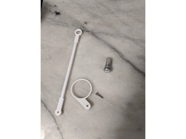
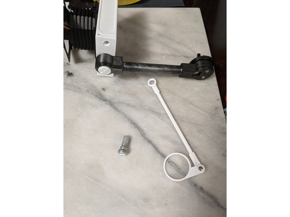
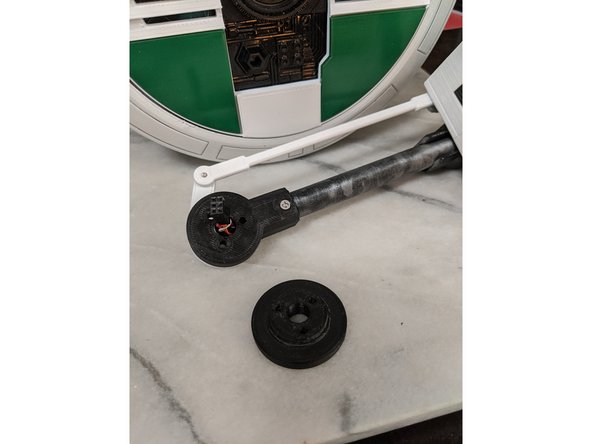
Here we will be working with the nod arm. For this, I used the NodArm and NodArmLever prints, and a #4 x 1/2" screw since it is what I had available.
-
Drill out the NodArmLever print so the screw passes through the hole but the threads to not bite into it, you want it to freely turn.
-
Drill the NodArm to a smaller diameter so that you can thread the screw into the NodArm and make your own threads with the screw.
-
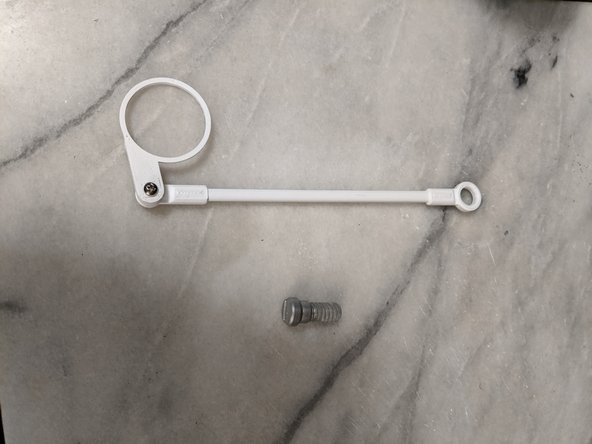
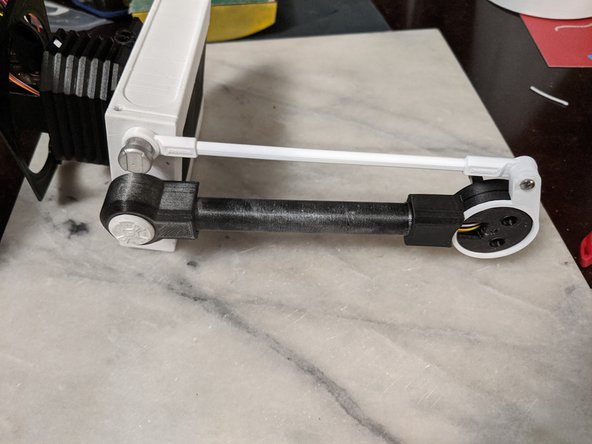
Attach the NodArmLever to the NodArm as shown in Pic 2.
-
Do not tighten the screw all the way so that the NodArm binds to the NodArmLever. You want to tighten it just enough so the NodArm still swings freely from the NodArmLever.
-
-
-
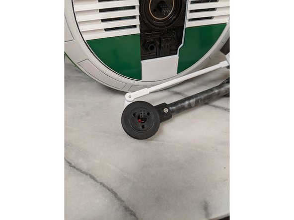
Here we will use the NodArm assembly you just made and the head assembly with the head bar attached. You will also need the NodBolt print.
-
The NodArmLever goes over the MainBarHolderA print that is attached to the bottom of the HeadBar.
-
Attach the top of the NodArm to the HeadBox with the NodBolt print as shown in Pic 2.
-
-
-
This step is simple since we installed magnets earlier.
-
Attach the FrontPanel Skin print to the body. It is only held on by the previously installed magnets. Not sure pics are needed, but here you go anyways.
-
-
-
Now we will prep the head assembly for attaching to the body. You will need the head assembly from the previous step, the MainBarHolderB print and 3x M3 x 35mm long countersunk screws.
-
The MainBarHolderB print has a large side and a smaller side. The large side will face the MainBarHolderA print as seen in pic 2.
-
Insert the 3 M3 x 35mm long countersunk screws through the 3 holes to hold the MainBarHolderB print in place as shown in Pic 3.
-
-
-
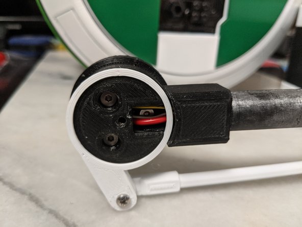
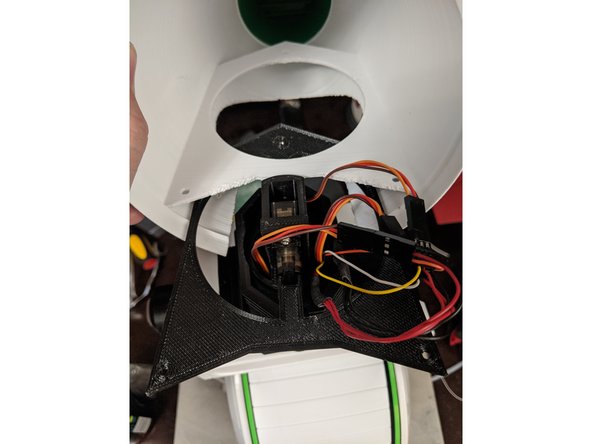
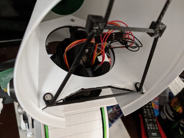
Here you will have your main body and the head assembly from the previous step. F
-
First you will want to plug in the harness from the head assembly into the plug previously made in the MainBar. Make sure to line the wires up how you wired them in the plugs so all the wires match properly. Matching the power and ground would be the easiest way to make sure. See Pic 2.
-
Next you will attach the head box assembly to the body using the 3 screws installed in the MainBarHolder prints from the previous step. Tighten the screws to hold the assembly in place as seen in Pic 3.
-
-
-
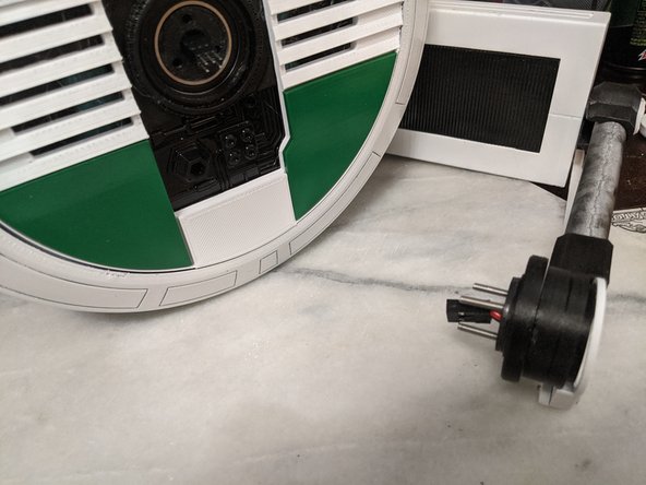
Here we will use the MainBarCap that has the epoxied screw in it that we made earlier.
-
You will use this to cover the MainBarHolder and this will also hold the NodArmLever in place. See Pic 2.
-
-
-
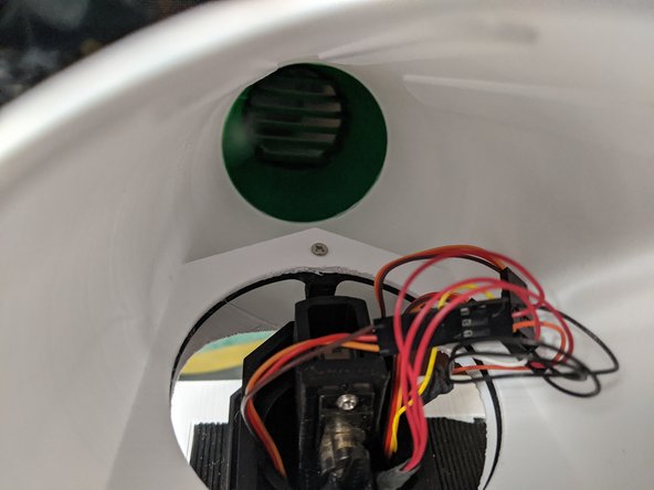
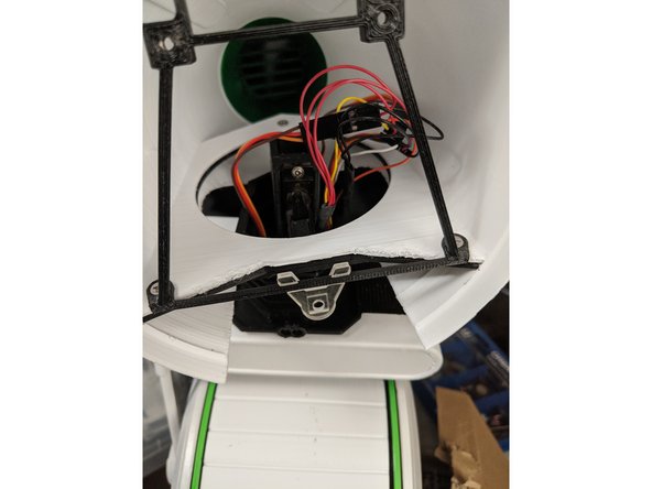
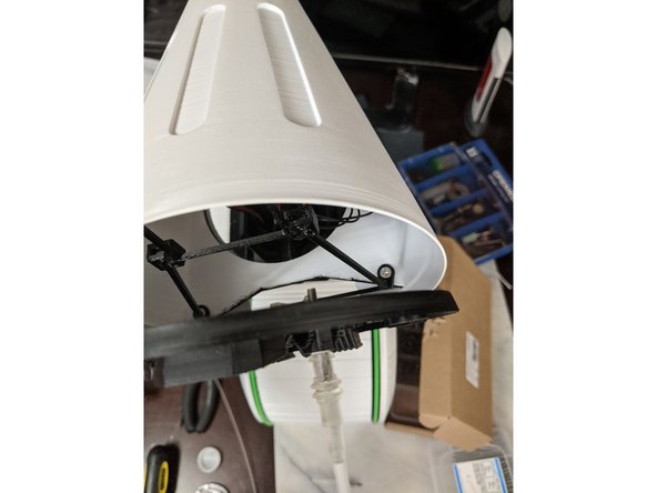
Here you will slide the head onto the HeadPlate.
-
The head will slide on as shown in Pic 1.
-
Make sure to keep the wires out of the way while you work the head over the servo mount and have everything come out through the center of the hole in the mounting bracket in the head.
-
Once the head is slid all the way on, use a M3 x 10mm long screw to attach the front of the mounting bracket to the HeadPlate. The HeadPlate has a captured M3 nut we previously installed. This is a tight area to work in, but using a screwdriver bit for a drill and screwing it on by hand worked for me.
-
-
-
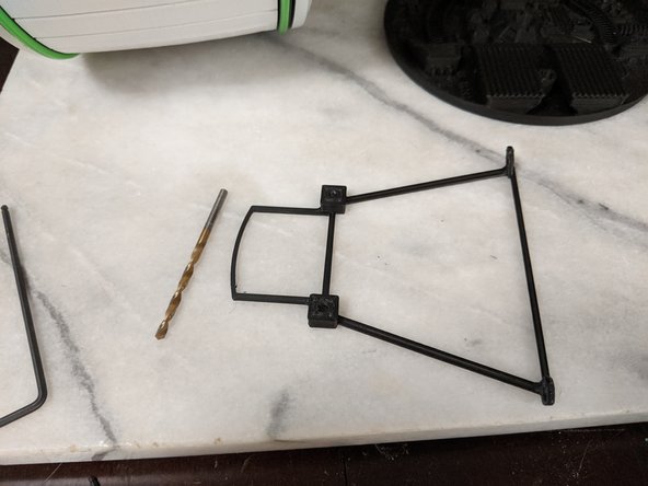
Here we will prep the RearFrame print. This is the bracket that will hold the back head panel on.
-
First drill out the holes for the screws so the screws do not bind when passing through the holes. I used a 1/8" drill bit.
-
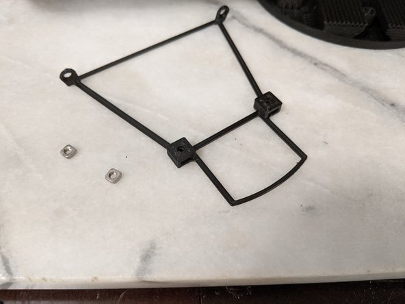
After the holes are drilled and any debris is removed from the pockets and holes are cleaned up, take 2 M3 Square Nuts and insert them into the pockets and line the threads up with the holes so a screw smoothly goes through.
-
-
-
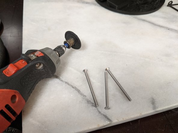
Here you will want a dremel with a cutting wheel and 3 M3 x 30mm (or longer if you choose) screws.
-
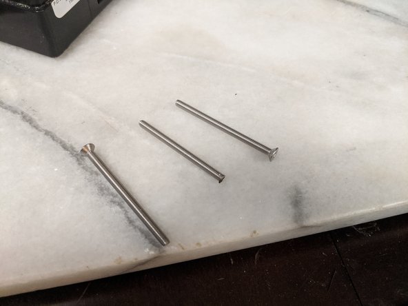
You are going to hold the screw with a pair of pliers and cut the head off the screw. The screw will get very hot so you will want to hold it with a pair of pliers while cutting or put it in a vice.
-
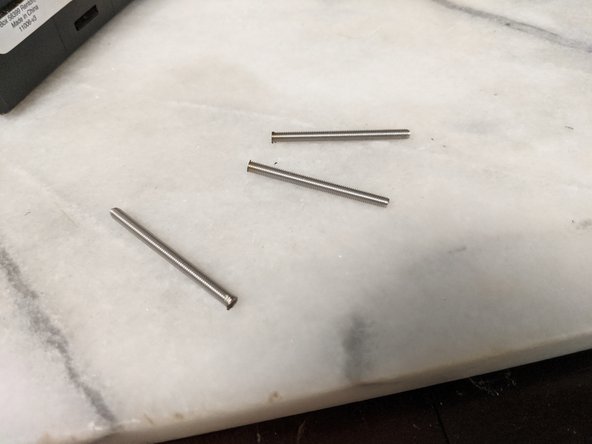
I used 30mm long screws which seemed to be a good length. If you used longer screws, cut the threaded rod length down to about 27-28mm long.
-
-
-
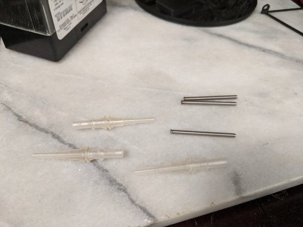
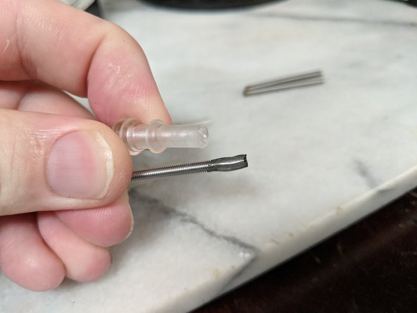
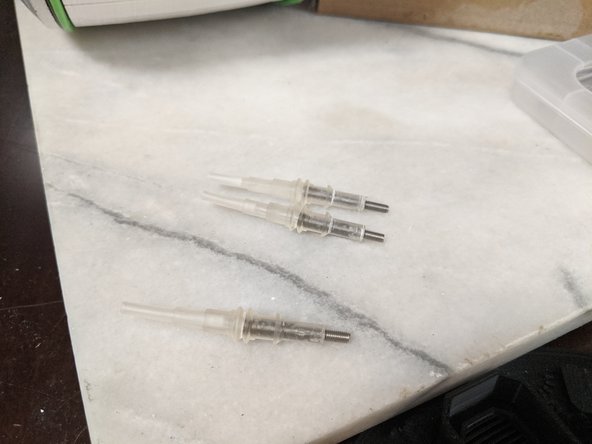
Here we will secure the threaded rod to the AerialBase prints. I printed mine in clear resin and have not painted it yet, but to get the guide further along, I'll paint it at a later date since they are easily removable.
-
The first thing I tried was epoxy, and if you printed these with a FDM printer, it would work great. Mine did not hold well, so I changed and used CA (super) glue. This held very well so you can use the adhesive of your choice.
-
Put the adhesive on the end where you cut. This way you do not try to thread the cut side onto the nut later. Also put a small drop in the print and insert the threaded rod into the print. Spin the threaded rod around to get a good coating of epoxy or glue inside and let sit to fully cure.
-
-
-
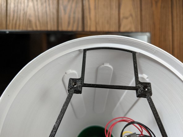
We will now install the RearFrame print into the head. For this I used 2 M3 x 8mm screws and they threaded into the bracket on the head and HeadPlate bracket as well.
-
Make sure the upper portion is behind the lip on the head as shown in Pic 2.
-
Use the 2 screws at the base to secure the RearFrame onto the brackets as shown in Pic 3.
-
-
-
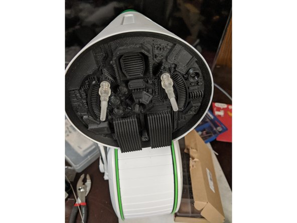
Here we will install the RearPanel print onto the head and finish out the assembly.
-
First clip the LowerAerialBracket print onto the bottom bar of the RearFrame as shown in Pic 1. There is a square cutout on the back of it for a M3 square nut that is easiest left till later to install.
-
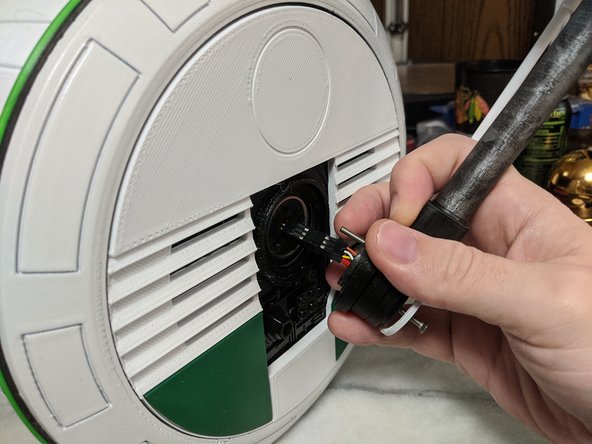
Insert one of the AerialBase prints with the threaded rod into the RearPanel, so the threaded rod sticks out the back..
-
Line it up with the hole for the RearFrame as shown in Pic 2 and thread it on by turning the AerialBase until it snugs up tight.
-
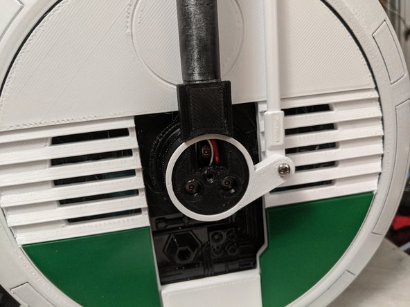
Insert another AerialBase into the other top opening and tighten it into the other hole as shown in Pic 3.
-
-
-
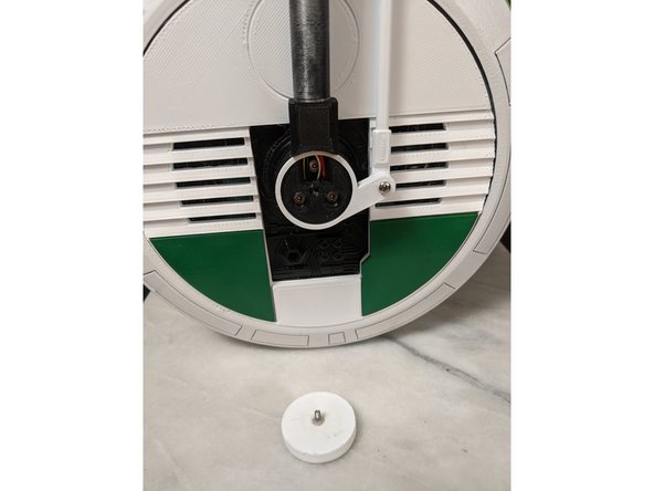
Take a M3 Square Nut and hold it with your finger into the notch of the LowerAerialBracket that can be seen from under the head in Pic 1. Hold the square nut in place with your finger.
-
Insert the third AerialBase into the lower hole of the RearPanel and screw it into the Square Nut you are holding in place. Tighten the AerialBase.
-
You should have all 3 AerialBase prints in place now as seen in Pic 2.
-
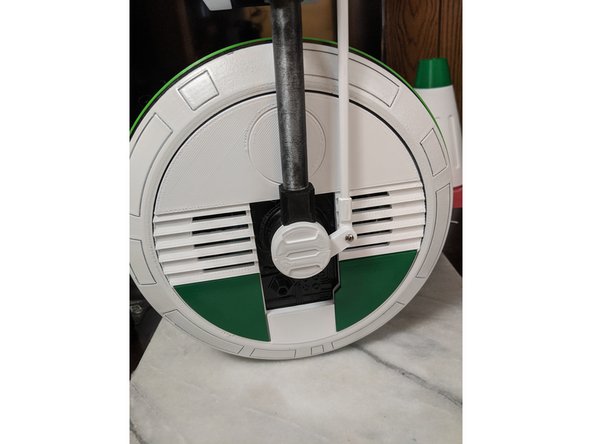
Pic 3 is reference showing the threaded rod of the lower AerialBase threaded into the LowerAerialBracket print.
-
-
-
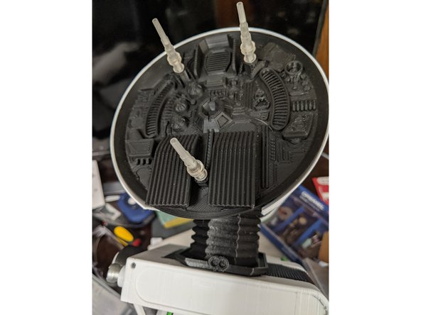
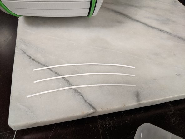
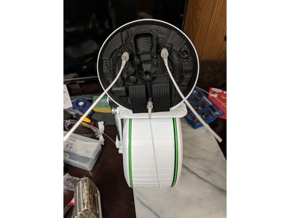
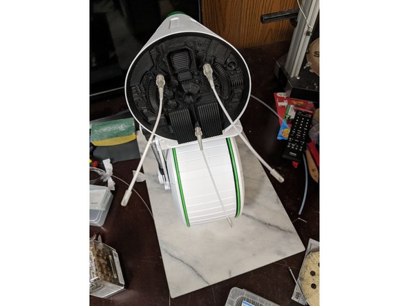
I used 3 pieces of filament to make the antenna. 1.75mm filament worked perfectly. I do not know the exact measurement so I went with what looked good. I used white filament that was approximately 115mm long and straightened it as much as possible with my fingers.
-
Using superglue, glue the filament into the AerialBase prints as shown in Pic 2.
-
Use a small drop of superglue to install the AerialTip prints onto the end of each filament as seen in Pic 3. This finishes out the antennas.
-
-
-
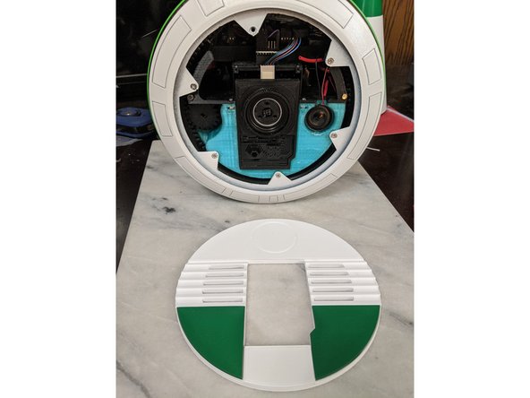
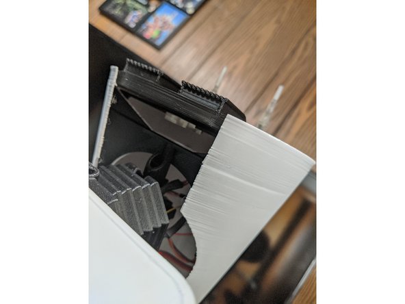
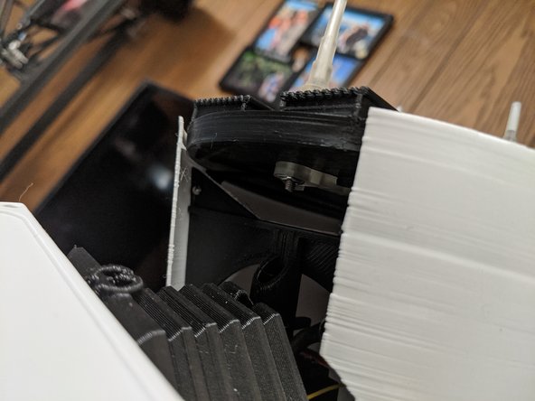
The other skin panel just attaches with magnets, and it is the panel that hides the power switch, so you will be taking it on and off when you want to power the droid on and off.
-
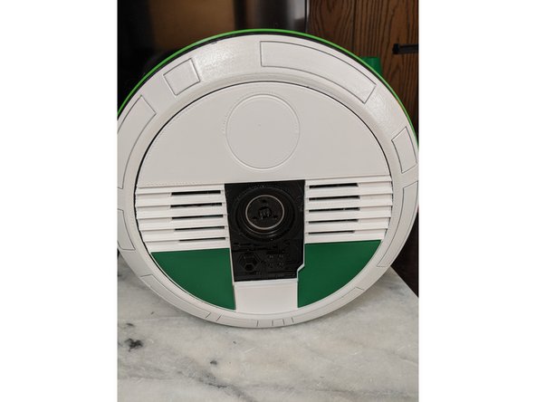
This is the final panel in the assembly. The droid is now fully assembled!
-