
Introduction
Support Michael Baddeley on his patreon page for files here: https://www.patreon.com/mrbaddeley/
If you wish to support the author of this guide, feel free to donate to me via paypal at http://paypal.me/guanu/
-
-
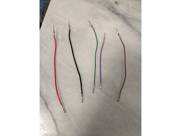
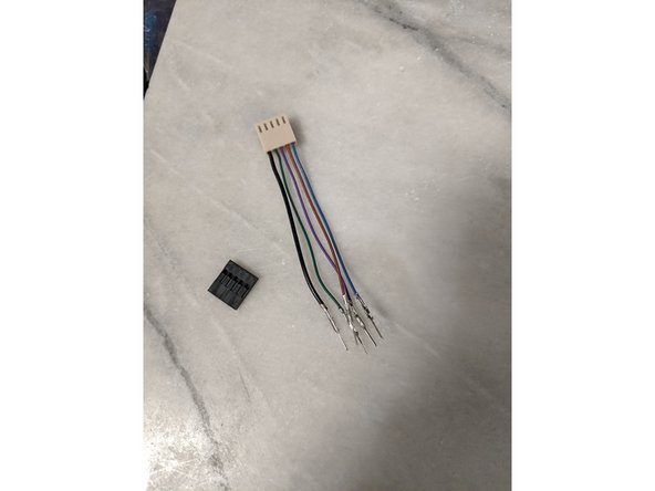
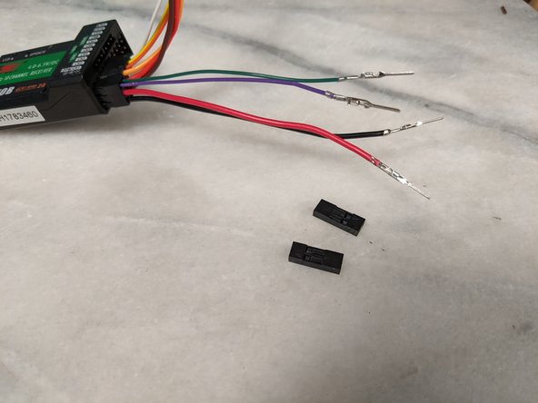
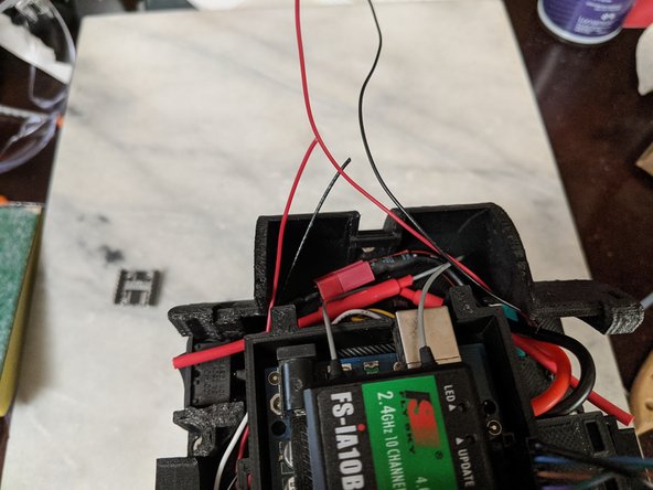
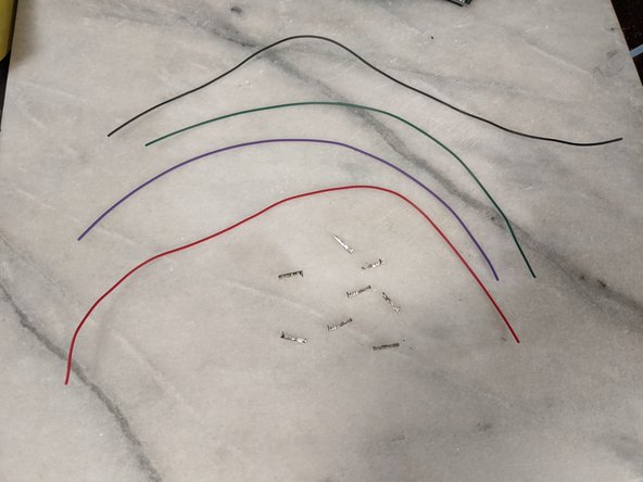
Here we will use the wire we trimmed off of the head bar to continue the wiring.
-
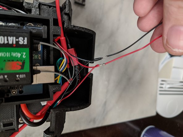
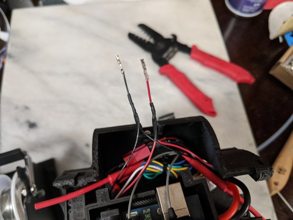
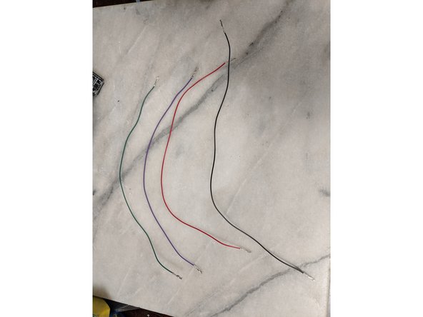
Using 5 Male crimps, just like the head wires, attach a crimp on each wire as seen in Pic 2.
-
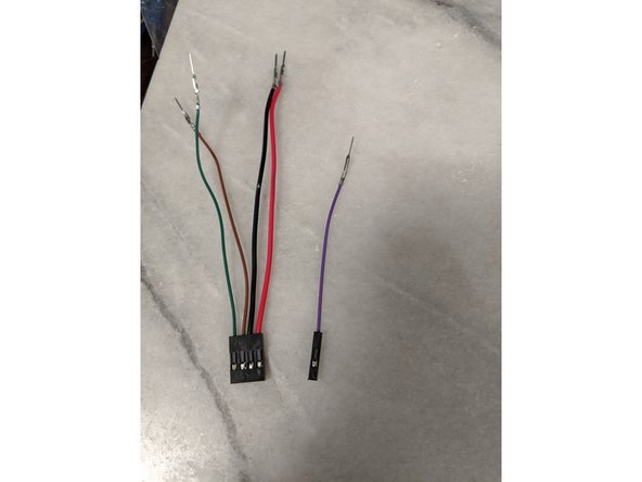
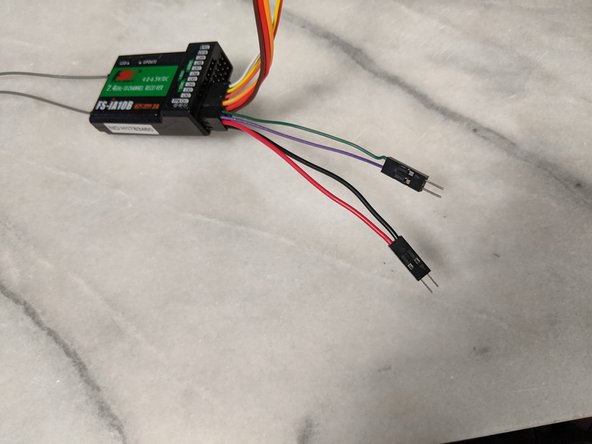
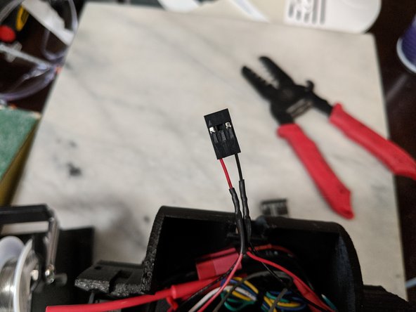
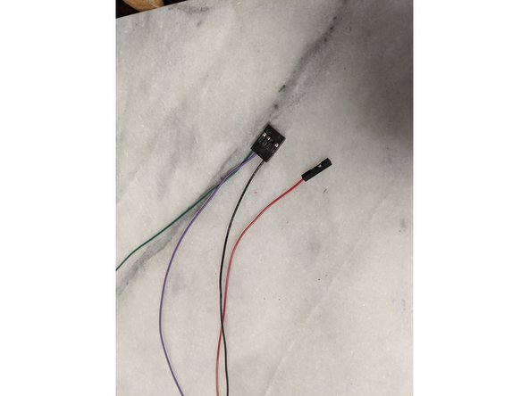
Here you will want to make sure you order the plugs so they match with the correct wire in the plug on the head. See pic 3.
-
-
-
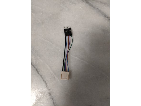
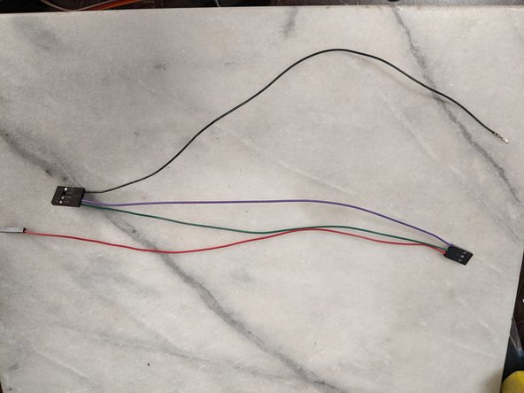
Limited to 3 pics per step, so I wanted to add this pic to show that you must make sure all the wires line up and all the colors match the correct locations.
-
-
-
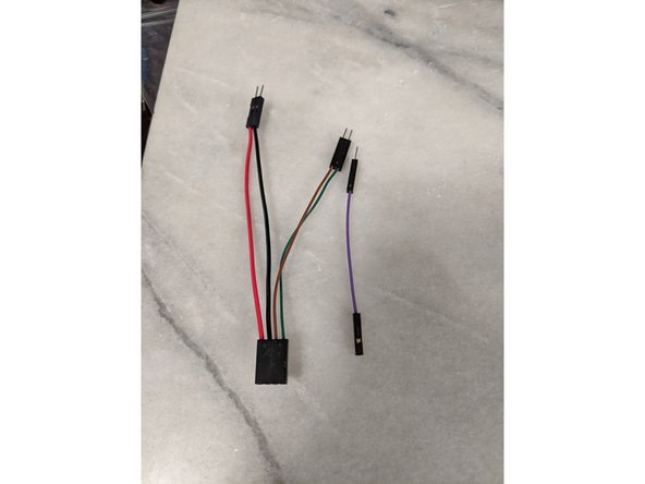
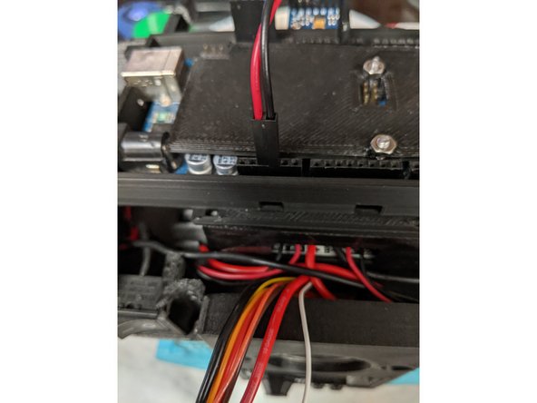
You will now take that section of wires and feed them through the center of the MainBar and out the hole located in the center of it.
-
The wires should exit as shown in Pic 2. and make sure the plug stays sticking out of the side where it will be plugged into the head wires as seen in Pic 2.
-
-
-
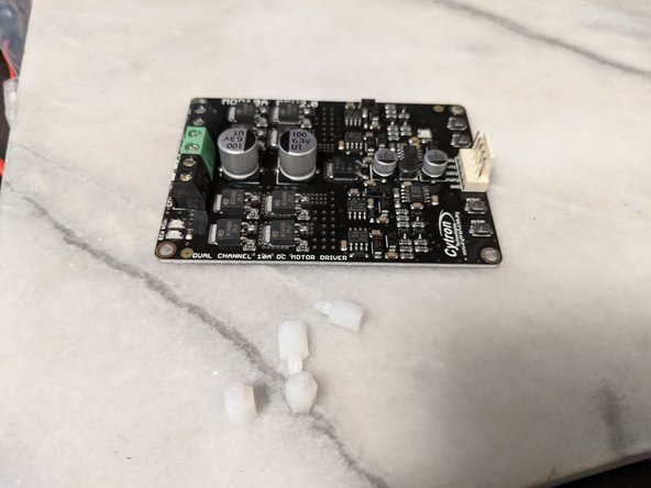
Here we will be working with the MDD10A motor driver.
-
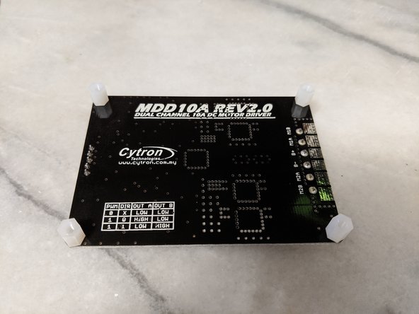
The motor driver will come with 4 white clips that have M3 threading.
-
Insert them from the bottom of the board into the 4 corners of the motor driver as shown in Pic 2.
-
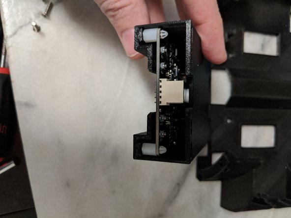
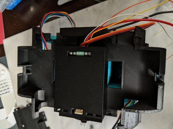
Insert the motor driver into the MotorDriverFrame print making sure the screw terminals are under the larger opening on the top, and the tan plug is lined up with the notch on the top of the print.
-
-
-
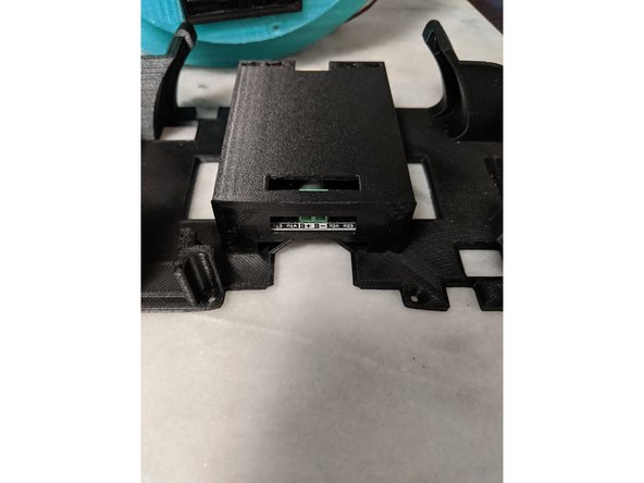
The Motor driver and MotorDriverFrame attach the the main frame with 4 M3 x 10mm countersunk screws.
-
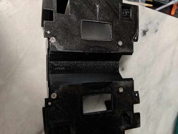
Make sure the MotorDriverFrame is orientated correctly. See Pics 1 and 3 for reference. There is a larger notch cut out of the TopFrame, and this is the side where the screw terminals on the Motor Driver will be located.
-
Attaching the screws as seen in Pic 2 is fairly difficult because the white parts that are threaded tend to spin on the motor driver when trying to tighten the screws. The way I did it was use a very long thin flat blade screwdriver to put pressure and hold the white threaded piece in place while tightening the screw.
-
-
-
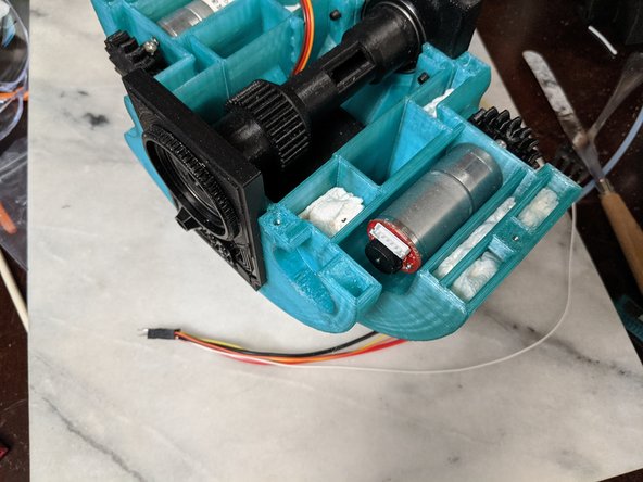
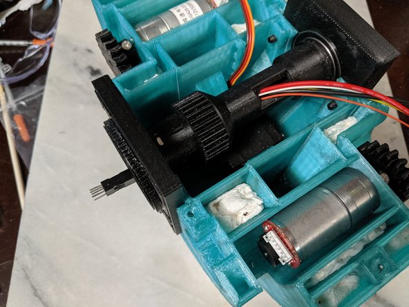
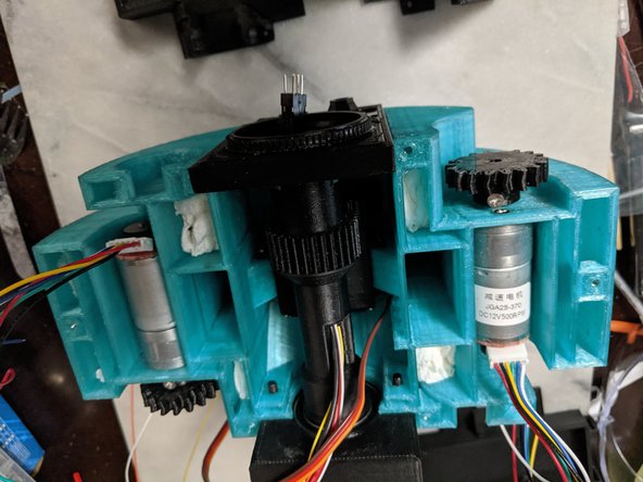
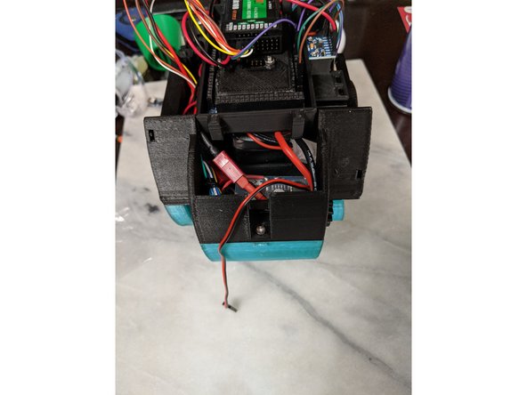
A few things to do before attaching the top frame on. First plug in the drive motor wires if your motors have pluggable wires. My motors are shorter than the ones Michael used, so I also had to bend back the plugs slightly as seen in Pic 1.
-
Also seen in Pic 1, you will want to take the wires coming out of the Main Bar and the center servo wires and pull them back to the side as shown in Pic 1 as well.
-
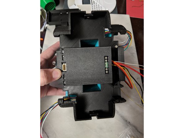
Place the TopFrame on the Frame, bringing the drive motor wires through the holes in the top frame, and the main bar wires and center servo wires will be in the notch on the side with the motor drivers screw terminals. This can be seen in Pic 2.
-
Using 6 M3 x 10mm long screws, attach the top frame to the main frame. There are 4 screws located near the corners of the motor driver frame, and one at each far end of the frame for a total of 6 screws.
-
-
-
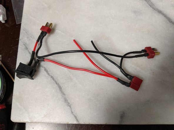
The next few steps will outline every wire connection I soldered for the power switch and battery plugs.
-
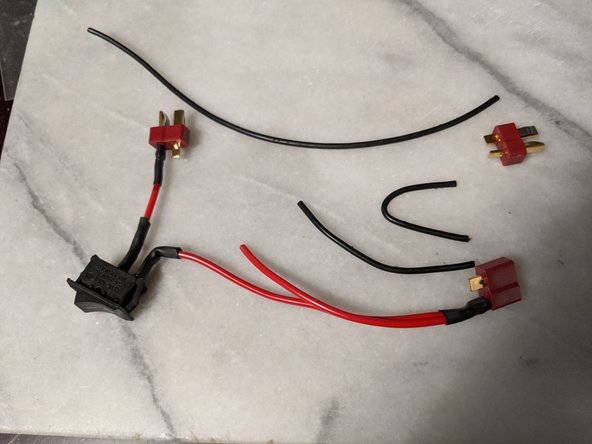
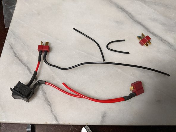
I will start with the positive wires.
-
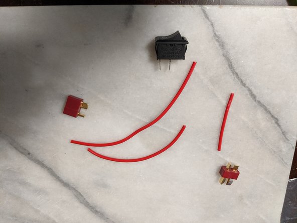
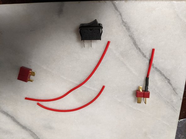
Using 3 wires, approximate lengths are 30mm, 70mm, and 110mm long. These are the main power wires, so do not use thin wires. I am using 18ga wires.
-
You will also need one male and one female T-plug Deans connector that matches the batteries used.
-
First connection will be the 30mm wire connected to the Positive pole of the male plug as seen in Pic 2. Make sure the wires go to the correct pins on the plugs so power all lines up properly!
-
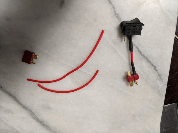
Attach the other end of the short wire to one of the legs of a rocker switch as seen in Pic 3.
-
-
-
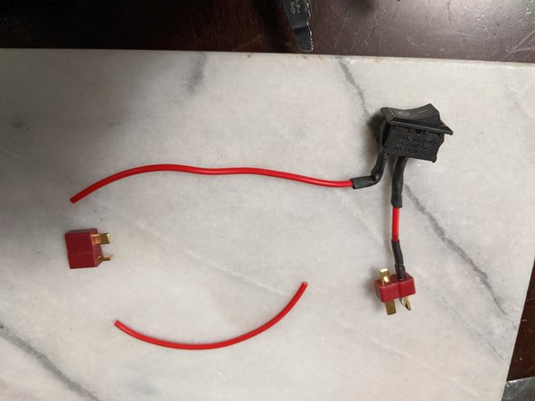
Attach the 110mm long wire to the other leg of the switch as seen in Pic 1.
-
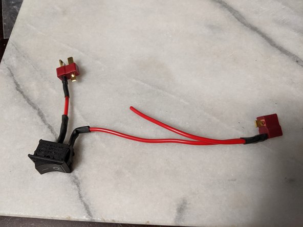
Attach the other end of the long wire and one side of the final wire both to the same pin of the female plug as seen in Pic 2. Make sure it is to the positive pin of this plug as well.
-
-
-
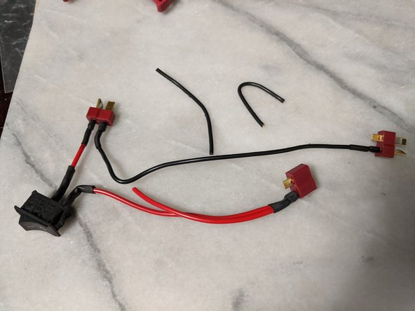
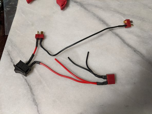
Now for the ground wires. Again 3 wires used. Lengths 160mm, 40mm, 55mm. You will also need another Male Deans connector as seen in Pic 1.
-
First attach the 160mm wire to the male connector shown in Pic 2.
-
Attach the other end of the 160mm wire to the other male connector that has no wires attached. Connect this wire to the POSITIVE terminal (we are wiring these batteries in series), it is correct as shown in Pic 3.
-
-
-
Attach the other two black wires to the remaining leg of the female connector as shown in Pic 1.
-
Finally attach the other end of the 40mm long wire to the ground leg of the other male connector as seen in Pic 2.
-
Your connector should look like Pic 2 in its final configuration.
-
-
-
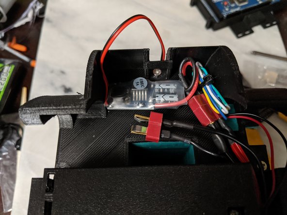
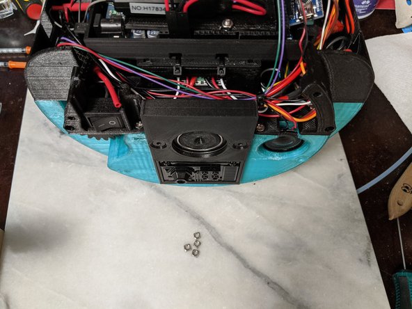
The power switch will slide into the TopFrame as seen in Pic 1. You can now see why the wiring was configured in the orentation we had it in during the previous steps.
-
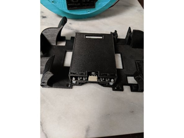
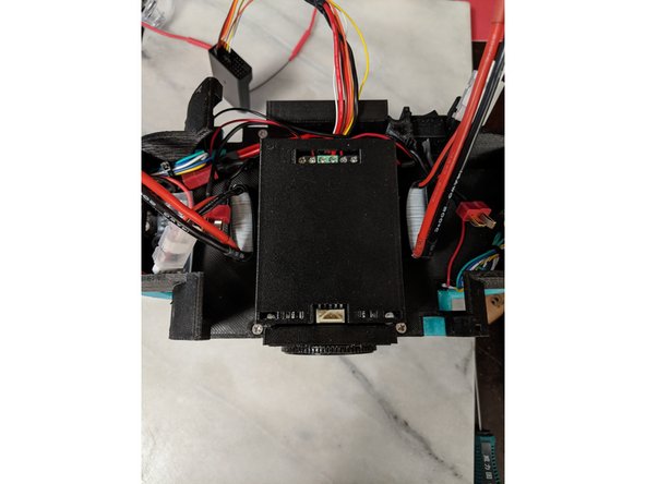
Strip the ends of the two final power wires, and they will attach to the center screw terminals on the motor driver.
-
See Pic 2 for the proper locations. When looking at the frame as shown in the pics, the positive wire will go to the center left terminal, and the ground will be the center right terminal.
-
-
-
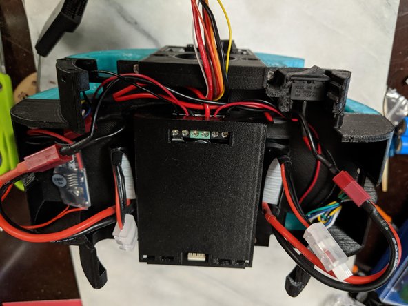
Here you will use the red and black wires from each drive motor and connect them to the Motor Driver.
-
I rolled up and put a zip tie on the remaining motor wires to keep them clean and out of the way.
-
The motors attach to the motor driver as shown in Pic 2 with the ground wires on the outside screw terminals, and the positive wires on the inside terminals.
-
-
-
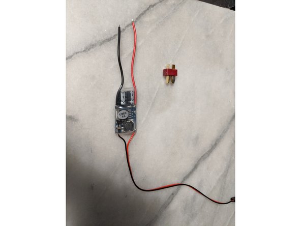
Here we will have a 5v 5A UBEC to control voltage to the rest of the electronics since we wired the batteries in series, they are over 14v and we need everything else to run at 5v.
-
Attach a male deans connector to the UBEC as shown in Pic 2. Make sure you have the correct wires going to the correct terminals as always.
-
-
-
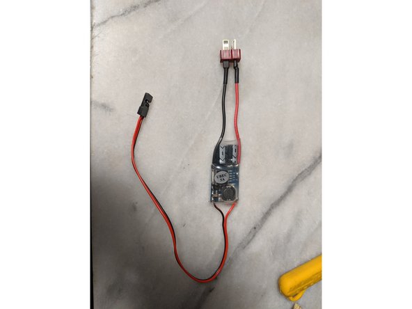
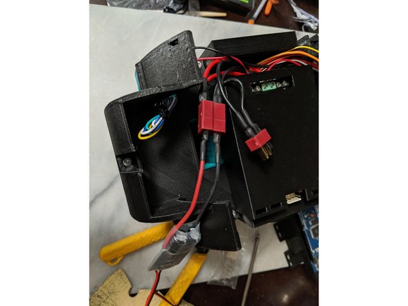
The UBEC plugs into the female plug on the power wire harness we made as shown in Pic 1.
-
I tucked the UBEC into the side of the frame as shown in Pic 2. You can also see my folded up wires from the motor zip tied and tucked away as well.
-
-
-
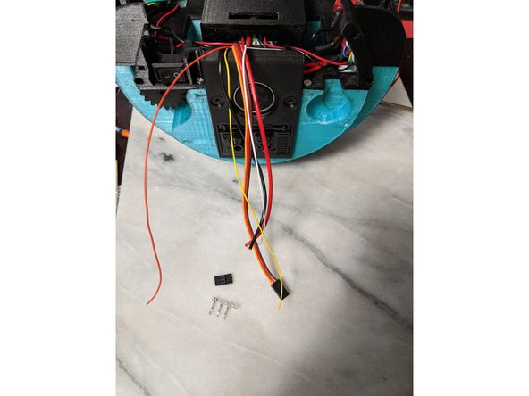
We will now work with the wires coming from the main bar that we bent to the side earlier.
-
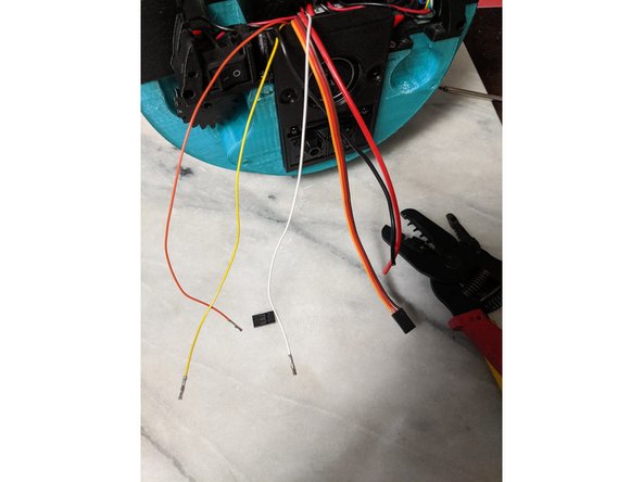
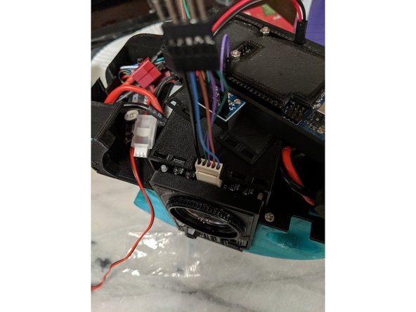
Strip the ends of the 3 thin servo wires and put on a female crimp on each one as shown in Pic 2.
-
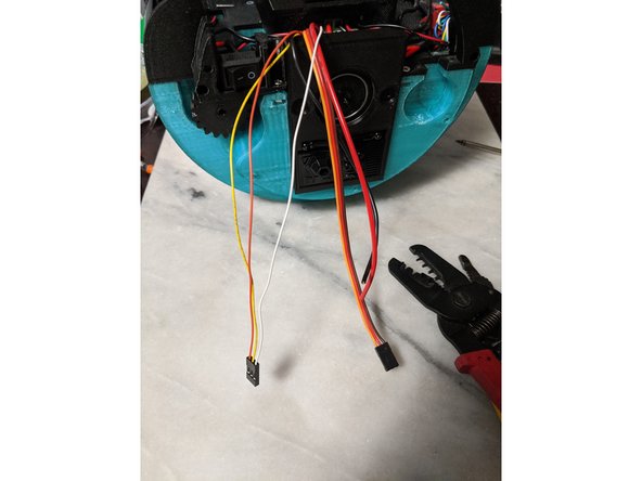
Put these wires into a 3 pin housing as shown in Pic 3. The order does not matter as we can assign switch channels on the RC remote later.
-
-
-
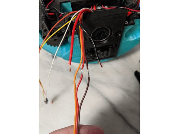
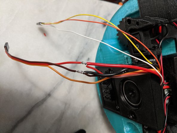
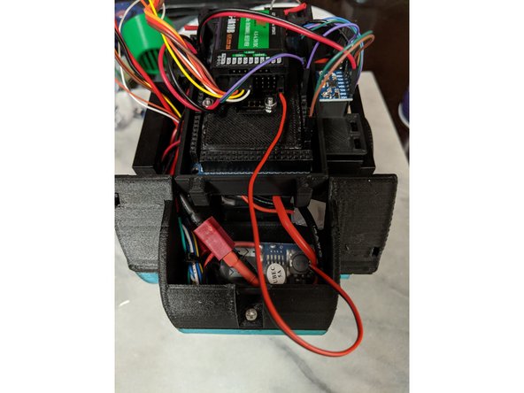
Here we will attach the power wires that go to the head servos to the servo wires that are attached to the servo in the center of the frame.
-
Carefully strip the power wires of the center servo. On my servo these are the red and brown wires. The third wire is the signal wire and it is typically yellow. Separate the wires and strip them as shown in Pic 1. I used an xacto knife to strip a section of the wire coating off.
-
Attach the power wires to the wires on the servo as shown in pic 2 and solder them on for a good connection.
-
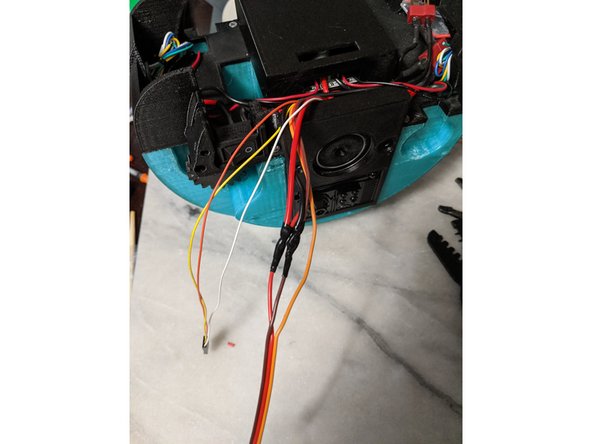
Secure the connection with electrical tape so the wires cannot short on each other or anything inside as seen in Pic 3.
-
-
-
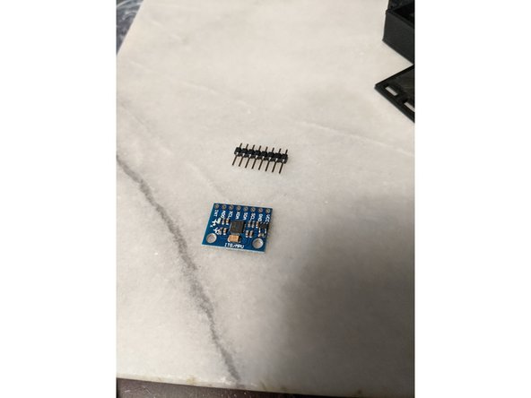
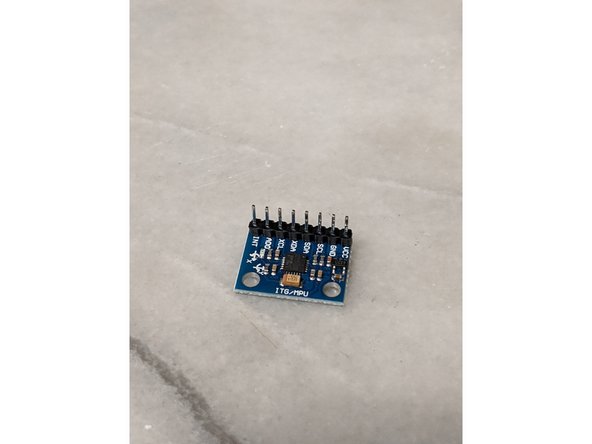
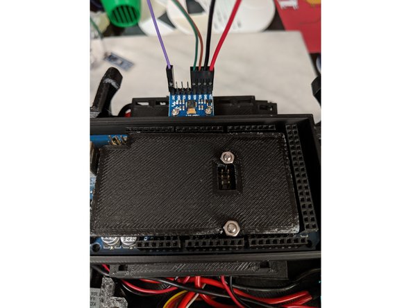
The GY-521 MPU-6050 comes with a heater. You will want to solder the straight header to the board as shown in Pic 2.
-
-
-
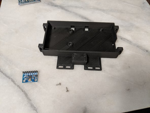
This will use the MPU, two small screws such as servo mounting screws, and the Arduino Base print.
-
Just a word of warning because I had to print the arduino base 3 times. The screws you will use to mount the MPU are thin and fragile. I broke the head off the screw twice even with the print so it could not be removed. I suggest using a small drill to drill out the holes but leave enough for the screw to bite the plastic and be secure.
-
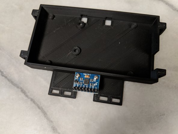
Attach the MPU with two screws as shown in Pic 3 to secure the MPU to the arduino base.
-
-
-
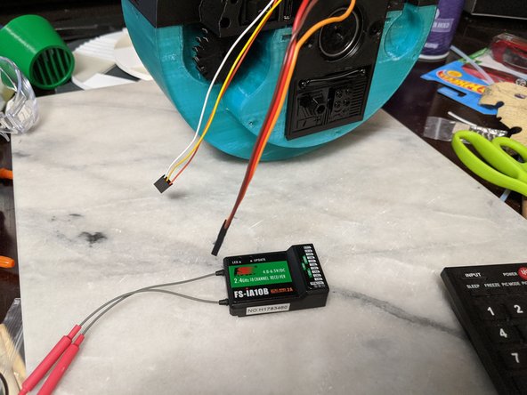
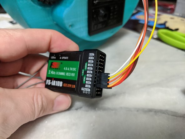
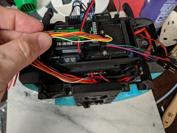
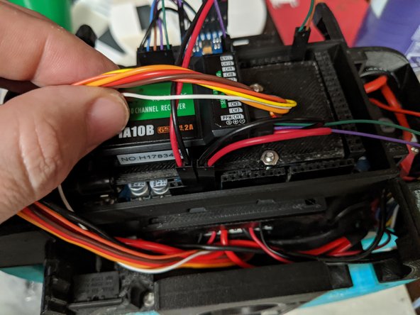
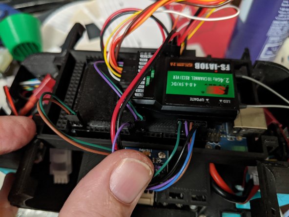
The Servo wires coming from the center can now be attached to the RC receiver.
-
The center servo with the power wires goes go channel 3. The remaining servo signal wires will be channels 4, 5, and 6. Use pic 2 as reference.
-
-
-
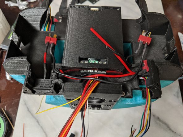
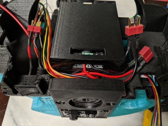
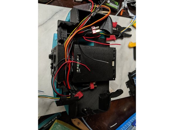
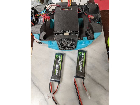
This step will use the fame so far and two 7.4 volt, 2200 mAh batteries.
-
They slide into the holes in the frame as shown in Pic 2.
-
Plug them into the two plugs we wired up with the main wire harness earlier and tuck the wires in the sides of the Top Frame to keep them out of the way.
-
-
-
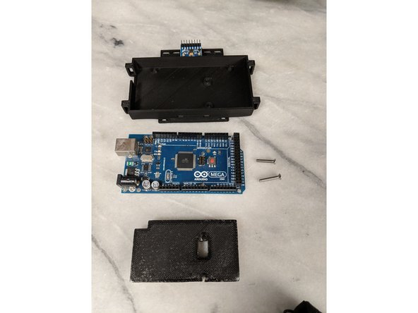
Here you will use the Arduino Base, Arduino Top prints and an Arduino Mega board. You will also need 2 m3 x 16mm long countersunk screws and two M3 nuts.
-
Place the Arduino Mega in the Arduino base so the USB lines up with the cutout of the base.
-
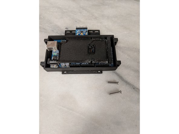
Place the Arduino Top on top of the Arduino lining up the cutout with the center pin header as shown in Pic 2.
-
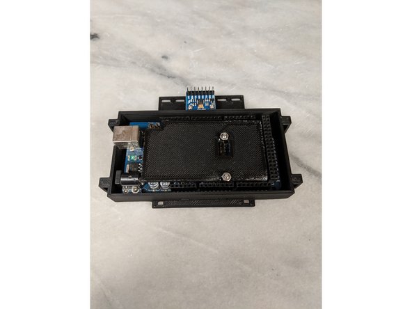
From the bottom of the Arduino Base, insert the 2 M3 x 16mm long countersunk screws through the base, through the arduino and out through the Arduino Top print. Lock it all together with a couple M3 nuts as shown in Pic 3.
-
-
-
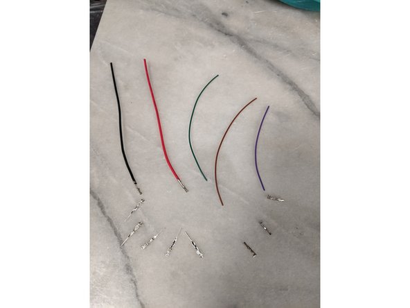
You will need 3 signal wires and 2 power wires. You will be crimping on 5 female crimps and 5 male crimps.
-
Each wire will get a female crimp on one end, and a male crimp on the other as seen in Pic 2.
-
You will use a 4 pin single row housing, and a 1 pin housing. Starting at one side of the 4 pin housing you will start with the positive wire, followed by the ground wire. Finish the 4 pin housing with two signal wires.
-
The single pin housing gets the last signal wire.
-
Your harness should look like Pic 3. The important part is having the positive and ground wires in the correct locations.
-
-
-
You will now use 3 housings, one single pin housing and two double pin single row housings.
-
We are now working with all the male crimps.
-
One two pin housing gets the positive and ground wires, the other two pin housing holds the two signal wires from the 4 pin housing.
-
The last one pin housing gets the last male crimp from the wire with the single pin housing. Your wires should look like Pic 1.
-
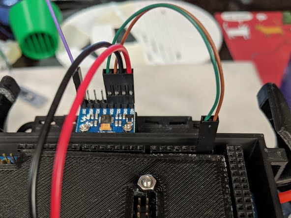
Connect the female housing onto the MPU as shown in Pic 2. The 4 pin housing will go on one side so the positive and ground wires line up with the correct pins on the MPU. The single signal wire goes to the last pin on the other end of the MPU as seen in Pic 2.
-
Now you can connect the positive and ground wires from the MPU to the GND and 5v pins on the Arduino as shown in Pic 3.
-
It has been brought to my attention that not all Arduino Megas have the same pinout. Mine has 6 pins in the first bank, others have 8. If your mega has 8 in the first bank, the pin locations will be the 5th and 6th from the left not 3rd and 4th as shown in Pic 3. If you go from the right side of the first bank of pins, it will be the same.
-
-
-
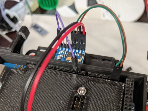
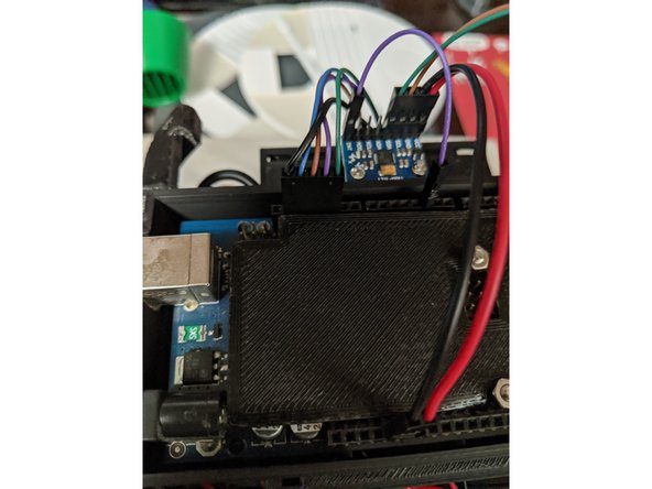
The other two signal wires on the 4 pin harness on the MPU connect to pins SDA and SCL on the Arduino. These two pins are labeled the same on the MPU. The pins will match the labels. SDA-SDA and SCL-SCL so they go to the correct locations as seen in Pic 1.
-
The single pin that is connected to the pin labeled INT on the MPU board will go to Arduino Pin 2. Use Pic 2 as reference.
-
-
-
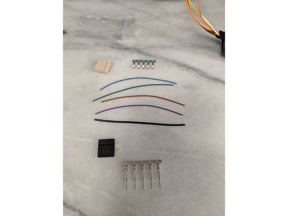
This step will use the crimps and housing that came with the motor controller in a small baggie. You will also be using a 5 pin single row housing and 5 male crimps. For wires you will use 4 signal size wires, and one ground wire.
-
Each wire gets a male crimp and a female crimp as before (you must be getting good at crimping by this point).
-
The tan housing that came with the motor controller will get all the female crimps. Use Pic 2 to reference which pin the ground wire goes into as this is important. The other locations get the signal wires.
-
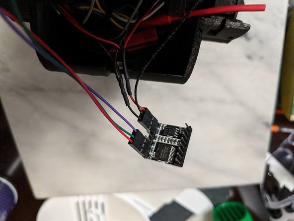
Now it is time to put the male pins into the 5 pin housing. Note the wire locations in this plug as shown in Pic 3. The ground will go to one end location. The difference is the order of the signal wires. They will be put in the 5 pin housing opposite the tan housing. So the signal wire next to the ground will go to the far location.
-
Your harness should look like Pic 3 so use that as reference as the correct wiring order.
-
-
-
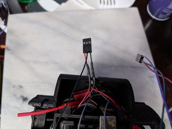
The plug on the motor controller only plugs in one way. This is why the ground wire location is important on this plug. See Pic 1 for reference.
-
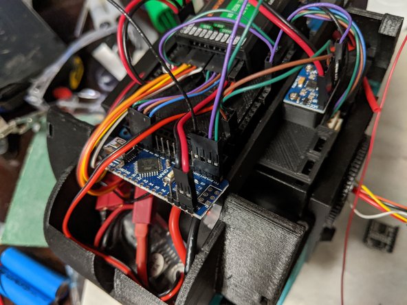
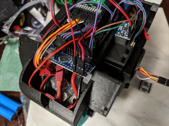
The 5 pin harness going to the Arduino will use pins GND, 13, 12, 11, and 10. Make sure the ground wire goes to the GND pin on the Arduino and it will be plugged in as shown in Pic 2.
-
-
-
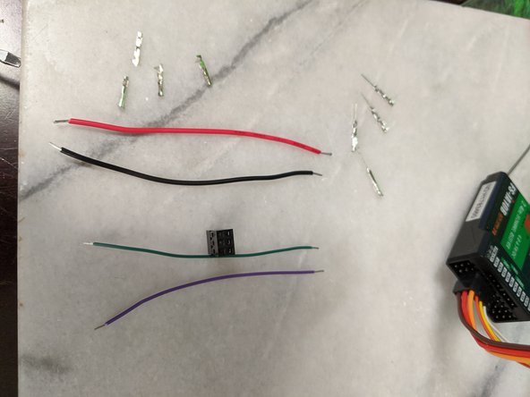
Now we will make a wire harness for the RC receiver to Arduino. You will use 4 wires. 2 wires are signal style wires, and a positive and ground wire.
-
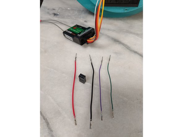
As before we will use 4 female crimps and 4 male crimps and each wire will get one female and one male crimp on each wire.
-
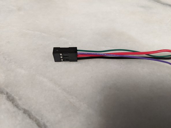
You will now use a 6 pin (2 row by 3 location) housing. You will want to use the female crimp ends of the wires and make the harness as shown in Pic 3.
-
One end of the harness will have the two signal wires, and next to one of the signal wires will go the positive and ground in that order as shown in Pic 3.
-
The other 2 locations in the housing are not used.
-
-
-
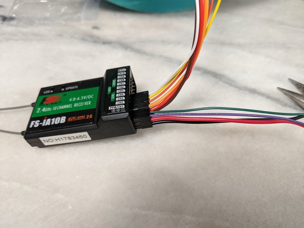
You can plug the harness into the receiver into channels 1 and 2 as shown in Pic 1. This will also connect the positive and ground wires to the receiver in one of the channels as well. These wires will power the arduino.
-
You will use 2 housings that are 2 pin each.
-
The signal wires will both go into one of the two pin housings, and the positive and ground will go into the other two pin housing as shown in Pic 3.
-
-
-
I used double sided tape to stick the rc receiver to the Arduino Top print as seen in Pic 1.
-
Pic 2 shows the location of the positive and ground wires coming from the receiver harness we just made. The positive will go the the VIN location of the Arduino and the ground will go to the GND location of the Arduino. Use Pic 2 as reference.
-
The two signal wires will go to Pins 3 and 4 of the Arduino. This will be next to the plug we put into pin 2 in an earlier step. See Pic 3 as reference.
-
-
-
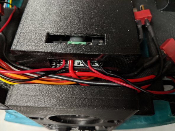
We will now connect the output of the UBEC to the RC receiver.
-
The UBEC will plug into the B/VCC port of the receiver. The middle pin is the positive and the lower pin is the ground.
-
See Pic 2 as reference to plug location.
-
-
-
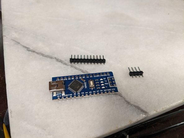
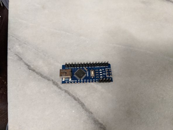
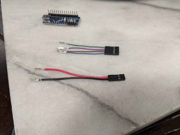
You will need an Arduino Nano and if yours did not come with the pins pre-soldered, it is time to attach them.
-
I only soldered on the ones I needed but you can solder all pins onto the Nano as well.
-
-
-
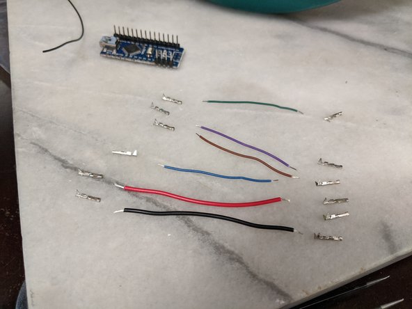
Time to build another harness!
-
You will have a power, ground, and 4 data wires used for this. All ends will have female terminals on them. You will use a 4 pin and a 2 pin housing as well.
-
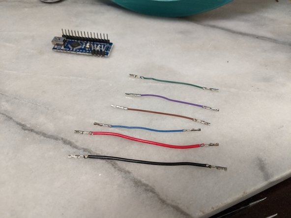
Attach terminals to the ends of all the wires as shown in Pic 2.
-
-
-
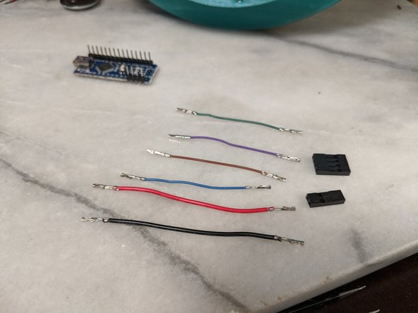
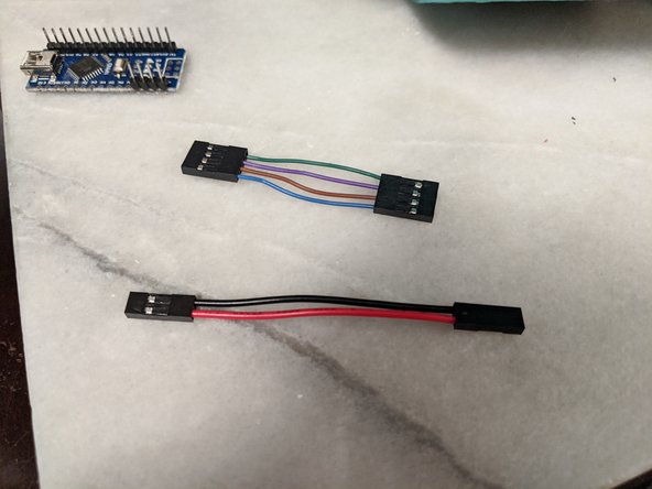
You will put a 4 pin housing on both sides of the data wires, and two pin housings for the power and ground wires.
-
Use Pic 2 as reference. The data wires can go in the same order on both housings as shown.
-
-
-
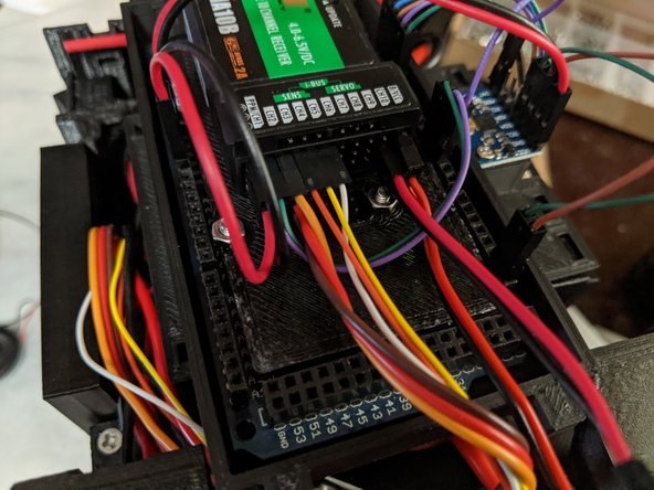
You will now plug these harnesses into the RC receiver.
-
First one to plug in is the power and ground harness. You can see I plugged it into channel 10. Note that the power wire is in the center of the 3, and the ground in in the bottom of the 3 for channel 10.
-
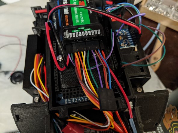
Next plug in the data wires. These plug into channels 7-10 as shown in Pic 2.
-
-
-
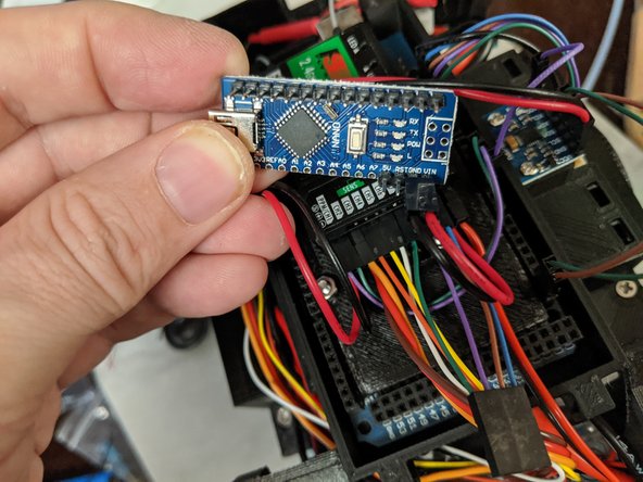
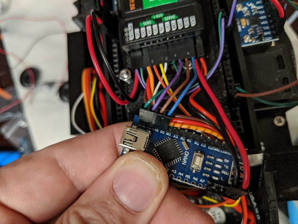
First you will plug the other end of the power harness into the VIN and GND pins of the Nano. Make sure the red wire goes to VIN and the black wire to GND. Use Pic 1 as reference.
-
The data harness will plug into the Nano next. These wires go to pins labeled D9-D12 as shown in Pic 2. If your nano is labeled differently, They still go in the same location next to the USB plug.
-
-
-
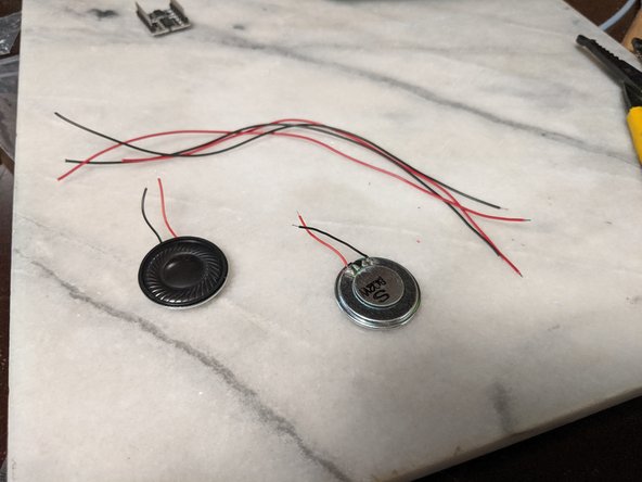
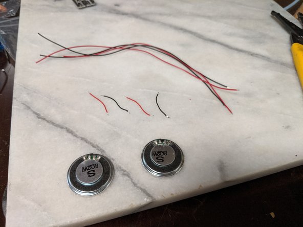
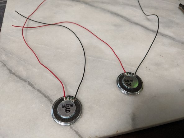
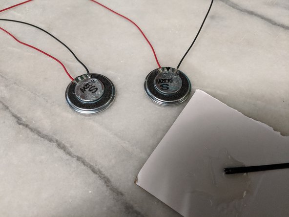
My speakers came with a tiny amount of wire on them which is pretty much useless, so I removed the wires and soldered on some longer wires.
-
The wires do not carry much power, so you can use data style wires for this.
-
Solder on longer wires so you have room to link them together as they are on opposite corners of the frame and need to be connected together since they are ran in parallel.
-
-
-
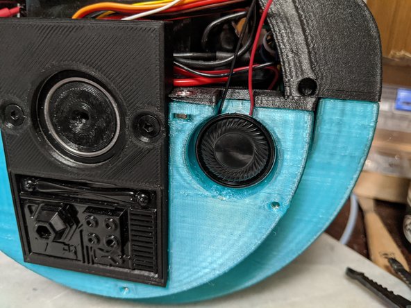
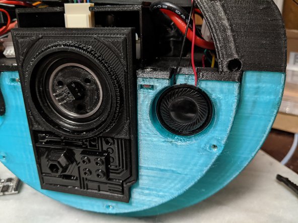
Here you can use your preferred method of attaching the speakers to the frame. I decided to use 2 part epoxy. If you wish you can use double sided tape.
-
Mix up some 2 part epoxy and put a small amount on the back of the speakers as shown in Pic 1.
-
As seen in Pic 2 and Pic 3, press the speakers into the frame with the wires coming up through the notch in the frame. Make sure the speakers are pressed against the frame well and perhaps use something to hold them in place while the epoxy dries.
-
Allow the epoxy to fully cure before moving on as you do not want them falling off.
-
-
-
Once the speakers are secured to the frame, it is time to route the wires to one of the sides of the frame. I picked the side with the most room so I have a space to tuck the audio board.
-
Solder the wires in parallel as shown in Pic 2. Red to red, black to black and having it come out as a single red and black wire.
-
-
-
More terminal crimping. Attach a female terminal to the speaker wires as shown in Pic 1.
-
Using a 3 pin housing, insert the speaker wires on the outer positions of the housing as seen in Pic 2.
-
-
-
Here we will be making a harness for the speaker board. This will use 4 wires, they can be all data wire size. You will have 2 data wires, a power and a ground.
-
All wires receive a female terminal as shown in Pic 2.
-
-
-
Here we will use a 4 pin housing, a 3 pin housing, and a 1 pin housing.
-
As seen in Pic 1, the power wire will be in the one pin housing. The data wires will be on one side of the 4 pin housing, along with a gap, then the ground wire in the last position of the 4 pin housing. as seen in Pic 1.
-
The ground wire will not have a housing on the other side of it.
-
The other side of the two data wires and the power wire will go into the 3 pin housing. The power will go on an outer pin, the data wire that was on the outermost position of the 4 pin housing will go in the center pin of the 3 pin housing, and the final data wire will be on the remaining location. Use Pic 2 as reference.
-
-
-
We will first plug this harness into the Arduino Nano.
-
The 4 pin housing plugs in first. The data wires will line up with the TX and RX pins, and the black wire will go to GND pin. See Pic 1 for details.
-
Next plug in the single housing with the power wire into the nano in the 5v position. This is on the side where you previously plugged in the VIN and GND wires, there is one pin between the GND and 5v that you will not use as seen in Pic 2.
-
-
-
The other side of the harness will now be plugged in.
-
Start with the ground wire that you did not put in a housing. This goes in the center pin of the housing the speaker wires went in earlier as shown in Pic 1.
-
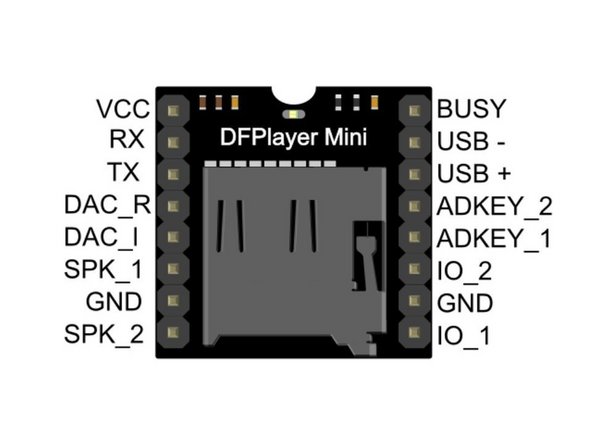
The mini sound board did not have any labeling on the pins at all so I had to look at the schematic. You can use Pic 2 for reference on how to plug it in.
-
I have included a pinout in Pic 3. You can see speaker wires and ground go to SPK_1, GND, SPK_2. note that SPK_1 is the positive for the speaker. The other harness goes to VCC, RX, and TX. Make sure the VCC is the power wire in the 3 pin harness.
-
-
-
Here you will secure the Arduino mount to the Top Frame.
-
There are 4 holes that will line up on the two mounts. I used these 4 spots for zip ties as shown in Pic 1.
-
On the other side, there are two locations I used for zip ties as well. These were much harder to fish the zip tie through, but it worked as seen in Pic 2.
-
-
-
Now is the time to clean up any wiring in the top frame. You want to make sure the wires are tight to the top of the the frame and secured as cleanly as possible so they do not get caught on the gear of the lazy susans when in motion. The wires near the IMU are ones particular that need to be as close to the frame as possible.
-
You will now install 4 M3 square nuts in the top frame. Each side has 2 locations for them.
-
-
-
Michael made a good overview video and I wanted to link it becauce is it worth a watch!
-
Here is the video: https://www.youtube.com/watch?v=qAdTprXg...
-
-
-
The electronics and wiring steps are now complete. The next section will have the steps for closing up the body of the droid and installing the lazy susans and main tire onto the droid.
-


Cancel: I did not complete this guide.
One other person completed this guide.
One Comment
I was just wondering about what transmitter you used and how do you make the droid make the sounds when it is turned on
John Glover - Resolved on Release Reply