
Introduction
Support Michael Baddeley on his patreon page for files here: https://www.patreon.com/mrbaddeley/
If you wish to support the author of this guide, feel free to donate to me via paypal at http://paypal.me/guanu/
-
-
Printed Parts: HeadBoxA, HeadBoxB, HeadBar, HeadFrame, ServoCouple, HeadBoxBar, HeadGreeble, HeadPlate, MainNeck, TopNeckMG90
-
Nuts and Bolts: TBD
-
2 part Epoxy
-
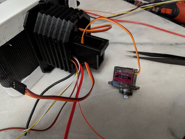
MG90S Servo - Qty 3
-
-
-
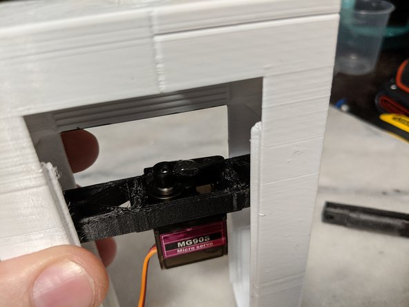
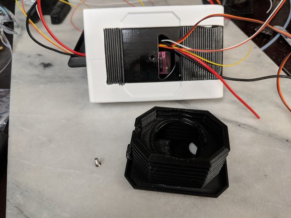
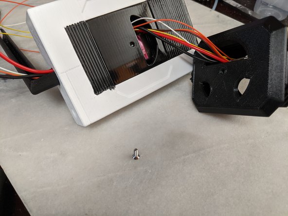
This step will use one MG90 servo, the 2 mounting screws that come with the servo and the HeadFrame printed part and 1 M3 Square Nut.
-
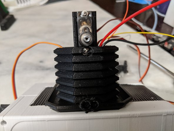
Screw the Servo into the HeadFrame in the orientation shown in Pic 2. The gear on the servo will be in line with the tab on the top. This tab will be positioned above the servo body.
-
Insert the M3 Square Nut into the slot on the tab on the top of the HeadFrame as seen in Pic 3.
-
-
-
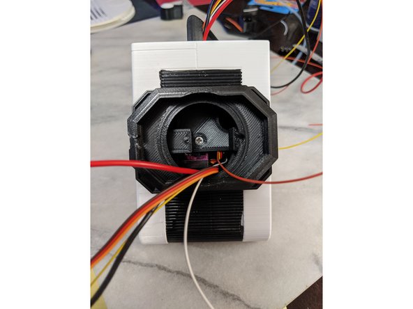
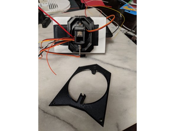
This step will use the HeadFrame with the servo attached in the previous step and the HeadboxA print.
-
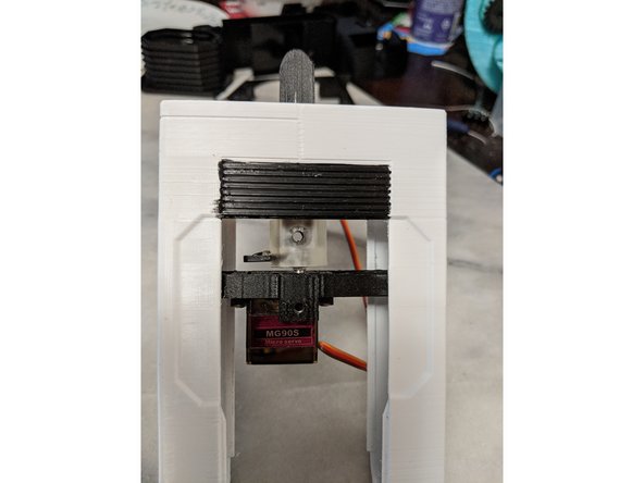
Insert the HeadFrame into the HeadBox and insert it into the slots inside the HeadBox as shown in Pic 2.
-
Make sure the orientation is as shown in Pic 2. The screw hole for the HeadFrame will be on the top. This is the side with the partial ribbed piece on the HeadBox along with the hexagonal indent on the top sides.
-
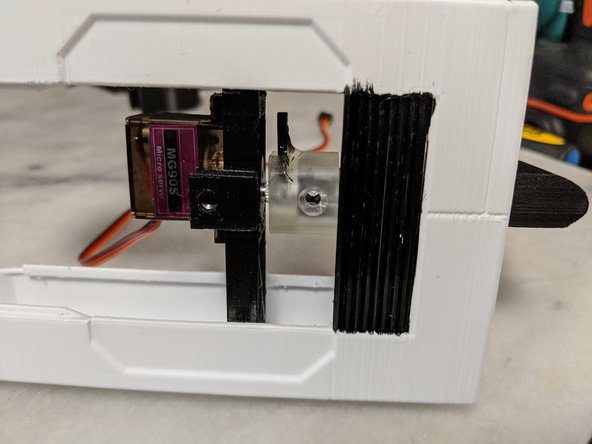
I used 2 part epoxy to secure the HeadFrame into the Headbox so nothing can slide around or fall out of the slots. This will still let me remove the servo for servicing but will secure the piece in place. I only used a small amount of epoxy on each slot of the HeadBox as shown in Pic 3.
-
Make sure the HeadFrame is fully seated in the slots and pause here to allow the epoxy to fully cure as you do not want it moving for the next steps.
-
-
-
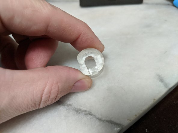
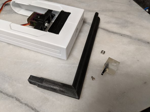
I planed on securing the servo horn to the ServoCouple print to make things more secure in the long run. For this I used a 9/32 drill bit to drill out the center hole on the ServoCouple so I can access the center screw on the servo to attach the horn/couple to the servo.
-
You can see the hole drilled out in Pic 2.
-
-
-
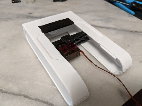
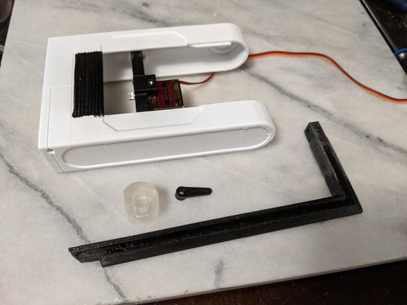
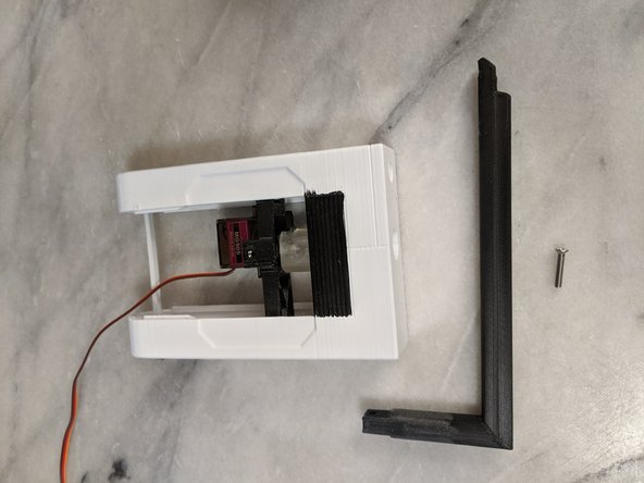
Here you will be using the servo horn, the ServoCouple print, the HeadBar print, and the Headbox from previous steps.
-
I would suggest reading through this and the next step and test fitting everything in place to make sure there is nothing you need to sand to fit. You can see on my HeadBar I had to sand the part the goes into the HeadBox to fit smoothly. You will have limited time once epoxy is mixed so test fitting is important!
-
Place the Servo horn so it is facing the direction of the body of the servo as shown in Pic 2.
-
Mix a very small amount of 2 part epoxy and put a drop on the arm of the servo horn. Make sure you do NOT put it in the center hole for the servo horn!
-
You can see the drop of epoxy I put on the servo horn in Pic 3. Quickly move to the next step before the epoxy cures.
-
-
-
Place the ServoCouple on the servo horn and seat it down as shown in Pic 1.
-
Note that the flat part of the ServoCouple print is on the top as shown in the pic.
-
Insert the Headbar into the Headbox and into the ServoCouple to hold everything in place, aligned, and fully seated and allow time for the epoxy to cure the ServoCouple to the servo horn.
-
The assembly while drying should look like Pic 2.
-
-
-
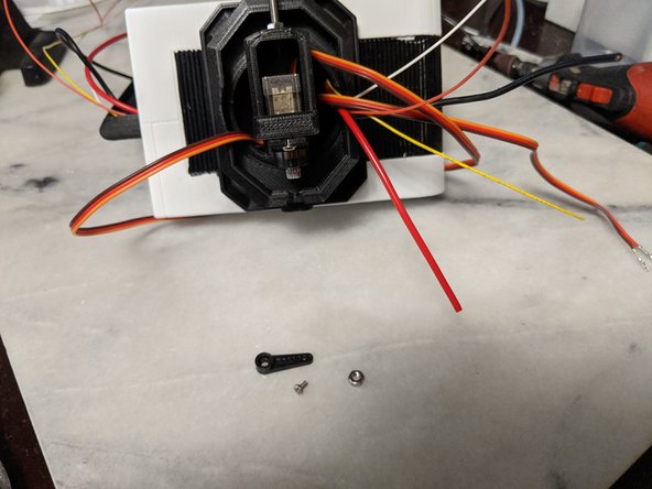
Once the epoxy has dried, remove the HeadBar, and remove the SeroCouple with the now epoxied on servo horn. You will use the servo center screw that came with the servo and a M3 Square Nut.
-
Insert the M3 Square Nut into the ServoCouple as shown in Pic 2. If it is loose, you can use some hot glue to hold it in place.
-
Place the ServoCouple with horn onto the servo in the same orientation of the previous step that you epoxied it on as.
-
Using the center screw that came with the servo, Install the servo horn onto the servo through the hole for the HeadBar as shown in Pic 3.
-
-
-
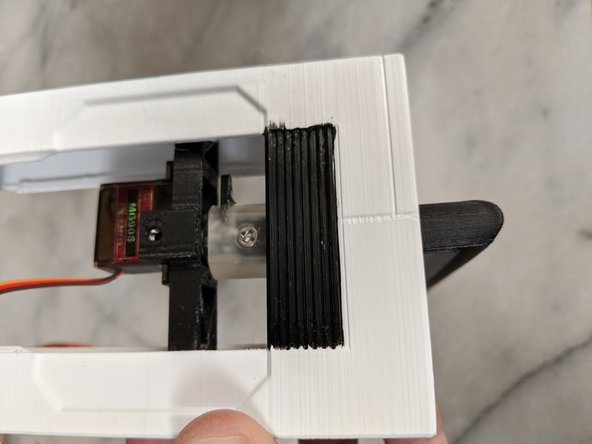
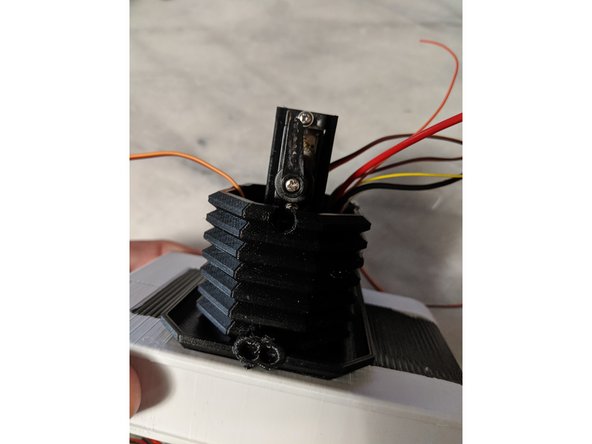
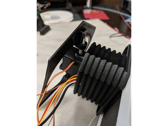
Here you will use the HeadBoxBar and the Headbox assembly you have made so far.
-
Insert the HeadBoxBar into the notches printed into the HeadBoxA print as shown in Pic 2.
-
If yours does not hold securely, you can place a drop of epoxy on each end to secure this bar into place. Mine seemed secure enough so I did not do this but may in the future to lock everything in place.
-
-
-
For the next step we will install the HeadBar to the HeadBox assembly.
-
You will use a M3 x 16mm long countersunk screw, the HeadBar, and the HeadBox assembly we have been working on.
-
Insert the HeadBar into the Headbox and into the ServoCouple until the hole through the HeadBar lines up with the Coupler as seen in Pic 2.
-
Use a M3 x 16mm long countersunk screw to go through the coupler and through the HeadBar and screw securely into the square nut installed previously into the coupler as shown in Pic 3.
-
-
-
There will be 3 servos in the HeadBox and Neck of the droid. The wires that come connected to these servos are not long enough to reach the electronics that will be installed in the body.
-
I had some spare motor extension wires that I will be using for this, but any 22-26 gauge wire will work, but use larger gauge wire for the power and ground. Each servo has a power, ground and pulse wire.
-
I used 5 total wires. 18ga red, 18ga black, 26ga orange, yellow and white. The reason for only one red and one black is explained in the next bullet.
-
I used 27 inch (686mm) long wires.
-
On the servo controller the power and ground are common to each other, so it does not matter which red and black go to which servo. Because of this, I am using one 18ga red and black wire for power and ground to the servos. Then I had orange, yellow, and white motor wires left for signal.
-
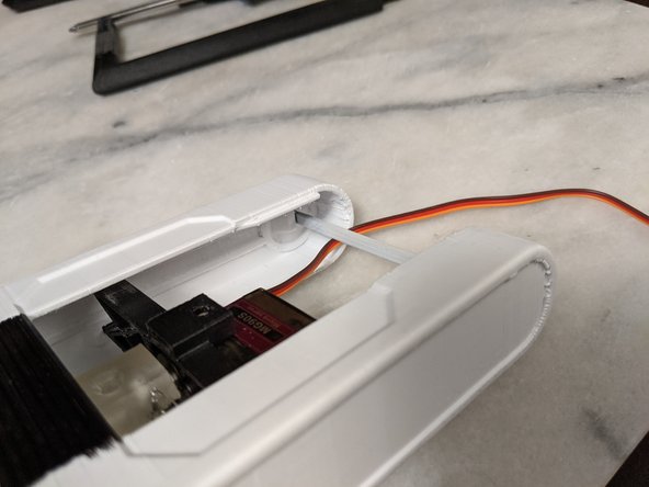
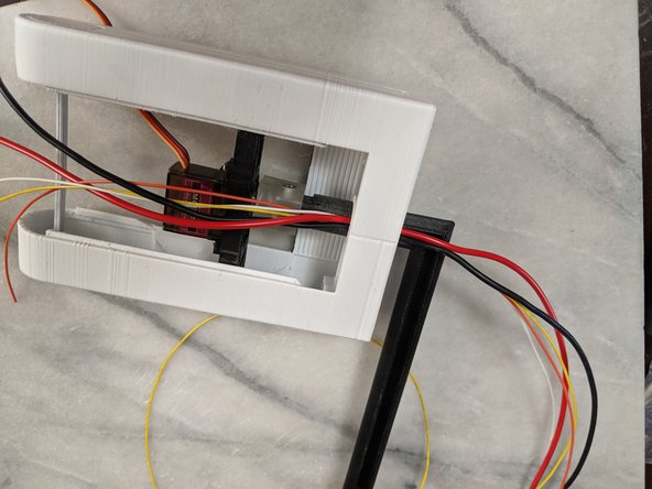
You can rotate the HeadBar so the channel is facing up like in Pic 1 to make it easier to feed the wires in.
-
Pic 2 shows the wires fed through. I left 7 inches (178 mm) of wire sticking out from the hole inside the HeadBox for the neck.
-
-
-
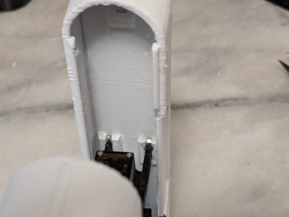
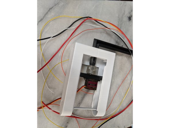
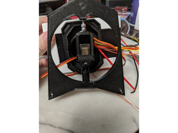
Here we now install the HeadboxB to cover the HeadBoxA opening.
-
As shown in Pic 2, feed the wires through the HeadFrame support.
-
While sliding the HeadBoxB over the HeadBoxA, feed the wires through the hole.
-
Slide the HeadBoxB skin all the way on. The bottom side should clip over a lip that is part of HeadBoxA and somewhat lock itself into place.
-
The hole on the top of HeadBoxB should line up with the hole and square nut installed in the HeadFrame.
-
-
-
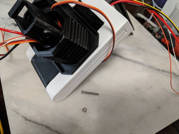
For this step you will use the MainNeck print and the HeadBox assembly.
-
Feed all the wires through the large opening of the MainNeck as shown in Pic 2.
-
The large hole the wires come through on the MainNeck will line up with the hole in the top of the HeadBox for proper orientation.
-
Using a M3 x 10mm long countersunk screw, attach the MainNeck to the Headbox. The screw will go through the MainNeck, the HeadBoxB skin, and into the HeadFrame where the square nut was previously installed.
-
-
-
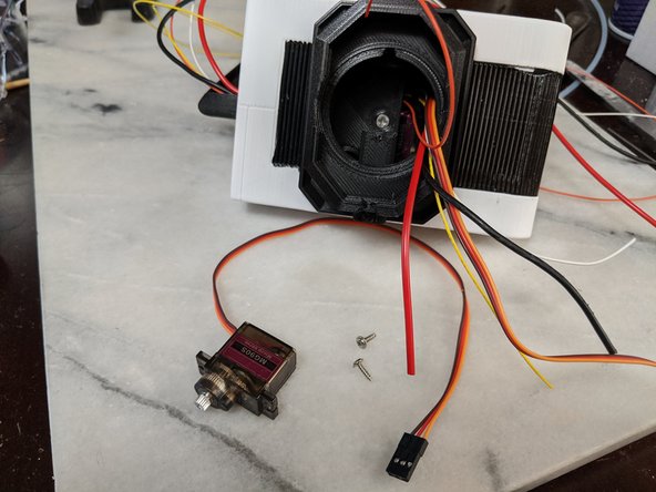
Here we will use another MG90S servo and the two mounting screws that come with the servo. Also you will want the single servo horn and machine screw that comes with the servo as well.
-
There is a notch in the neck for the servo wires so they do not get pinched. You can see this location in Pic 2.
-
Insert the servo as shown in Pic 2 and secure with the mounting screws.
-
Attach the servo horn to the servo as shown in Pic 3 and secure with the machine screw that came with the servo.
-
-
-
Here you will use 2 part epoxy to secure the servo horn to the TopNeck print.
-
Looking at Pic 1 you can see to apply a small dab of epoxy on the servo horn and the TopNeck print. Make sure not to put epoxy on the screw securing the servo horn to the servo so everything can still be removed if needed.
-
Place the TopNeck print on the servo horn and fully seat it and make sure it is level or lightly riding on the neck print. I applied a little more epoxy on the top of the servo horn as seen in Pic 3.
-
Let the epoxy fully cure before moving on.
-
-
-
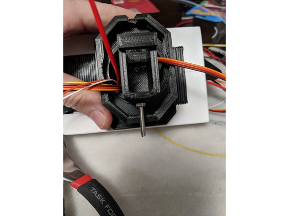
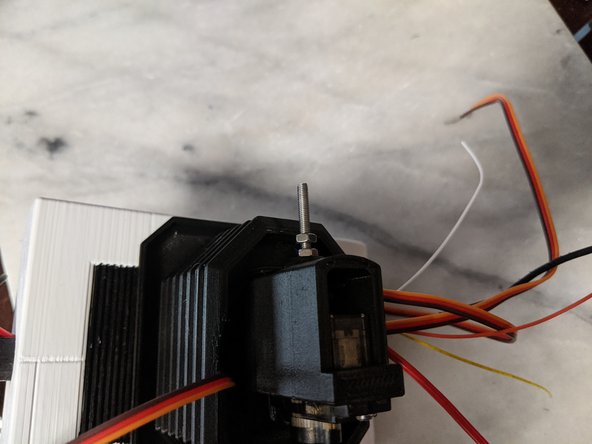
Here you will use a 25mm long M3 countersunk screw and two M3 nuts. I ended up changing these to lock nuts since I had them and suggest if you have them, you do the same
-
Insert the screw from the inside of the TopnNeck and secure with one nut as shown in Pic 2. Again, I changed mine out to a lock nut so nothing loosens from vibration.
-
Tighten the first nut to secure the screw in place securely.
-
Screw on a second nut (or lock nut) but do not fully tighten it to the previous nut. This nut will be used on a later step,so we are just putting it on for now.
-
-
-
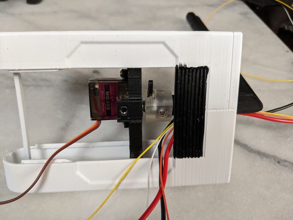
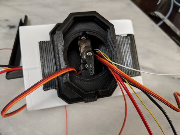
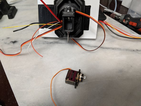
Here we will use another MG90S servo and the two mounting screws that come with the servo.
-
Feed the servo wires through the hole in the TopNeck print as shown in Pic 2.
-
Insert the servo into the TopNeck print and secure with the mounting screws as shown in Pic 3. There is a hole in the main neck print for a screwdriver to secure the servo with the mounting screw.
-
-
-
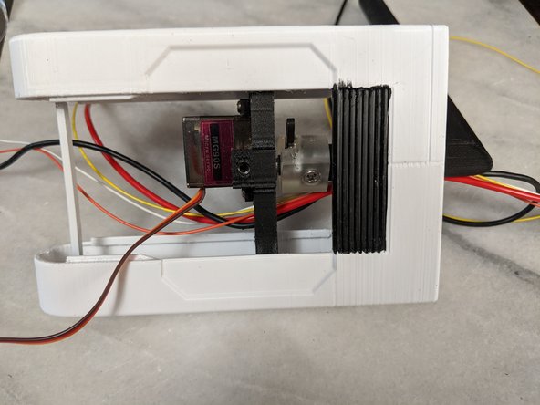
This step is simple, but since I'm limited to 3 pics per step, here it is. You will mount the servo horn on the Servo you just installed.
-
Install the servo horn facing up as shown in Pic 2 and secure with the machine screw that comes with the servo.
-
-
-
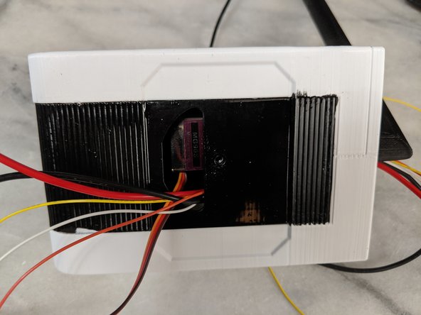
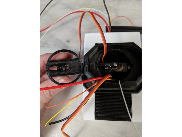
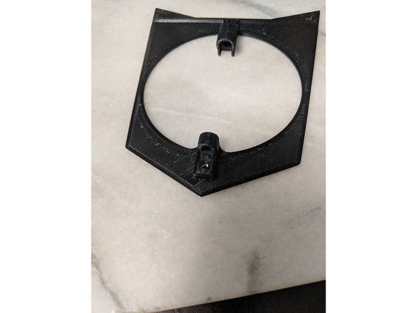
Here we will install the HeadPlate.
-
First thing you need to do is drill the hole on the front of the HeadPlate so a screw can go through it. I used a 3/32 drill bit.
-
Install a M3 Square nut into the slot as shown in Pic 3.
-
-
-
Insert the screw mounted to the TopNeck though the hole in the HeadPlate as shown in Pic 1.
-
Line up the servo horn with the cutout on the Headplate and push the servo Horn into this cutout as shown in Pic 2.
-
You will not need to epoxy this servo horn on, as it will be secured in place with the second nut we installed earlier on the screw.
-
Loosen the second nut (or lock nut like I used) until it meets the HeadPlate. You do not need to tighten this, as this screw will just prevent the HeadPlate from moving back and forth on the screw and servo horn. Pic 3 shows the nut holding the HeadPlate into place.
-
-
-
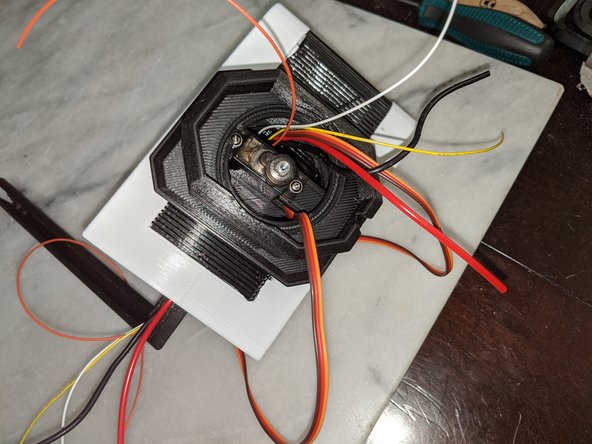
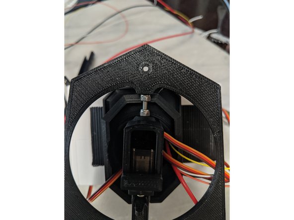
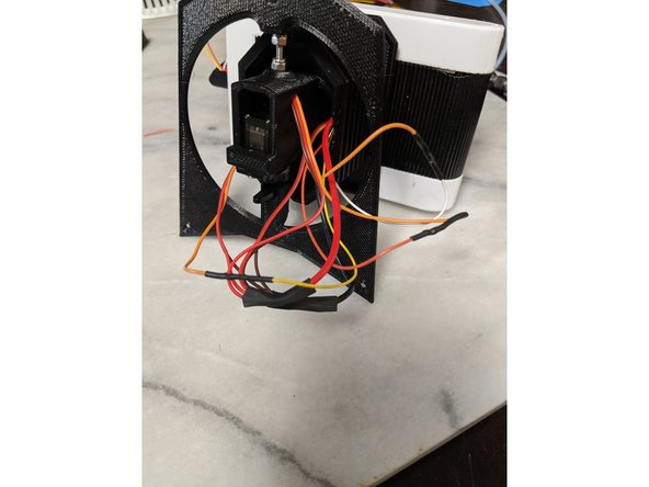
Here we will do all the wiring connections in the head for the 3 servos.
-
Cut all the wires to about the same length as seen in Pic 1. This will cut off the ends of the servos, keep these as we will use them later.
-
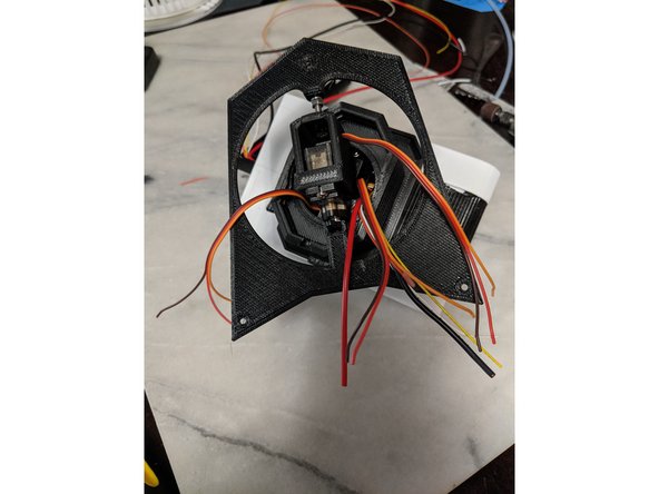
The servos have 3 wires, mine are orange, red, and brown. Separate the servo wires and strip the red and brown wires back about 1/4" and combine the 3 servo red wires and the 3 servo brown wires (some servos have black as ground). Also strip the large red and black wires that will go to the body. Use pic 2 as reference.
-
If using heat shrink, place it on the large red and black wires now.
-
Twist the combined red servo wires with the large red wire going to the body and twist the combined brown (or black) servo wires with the large black wire going to the body and solder the connection as shown in Pic 3.
-
Slide the heat shrink over the connection and heat to shink the heat shrink over the connection. If you do not have heat shrink, use electrical tape over the connection. I suggest 3M Super33 electrical tape.
-
-
-
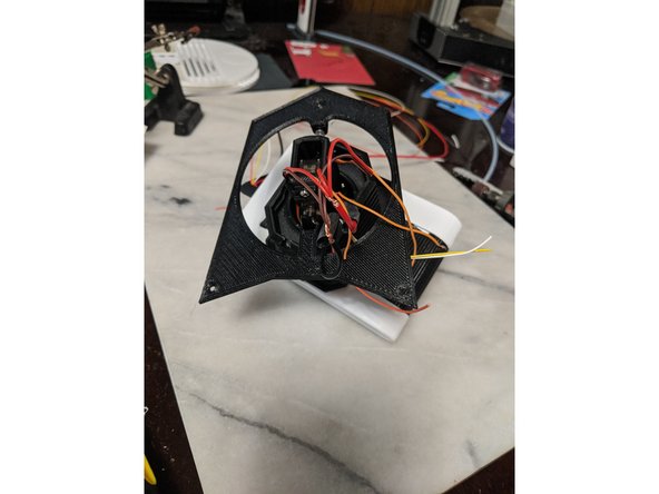
Here we will strip all the orange signal wires on the servos, and the other 3 wires going to the body. I have white, yellow, and orange that I used.
-
Each wire will go to a single servo for signal. You can look at where the wire goes to know which servo you are working with. The wires going into the HeadBox, the neck, and the third servo for the HeadPlate. Strip all remaining wires (there will be 6) as shown in Pic 1.
-
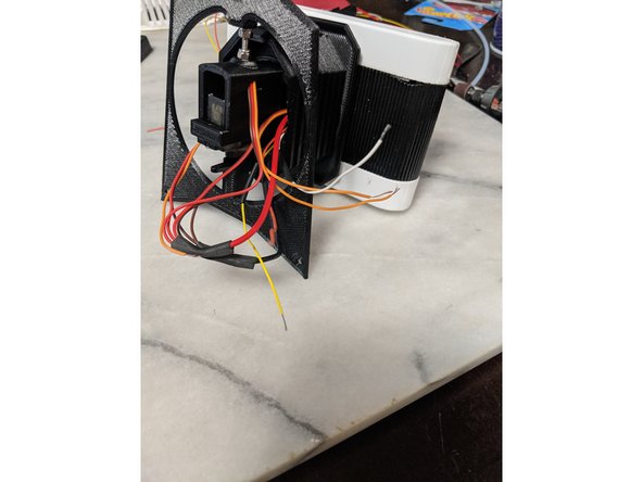
The connections I did was white wire - orange for the servo in the HeadBox, Yellow wire - Orange wire for the servo in the Neck, and Orange wire - Orange wire for the servo that runs the HeadPlate.
-
If using heat shrink make sure to place it on the wire before twisting and soldering. Then match the servo signal wire with the wire going to the body and solder the connection as seen in Pic 2.
-
Write down what color wires go to which servos for signal or label your wires that go to the body on the far ends of the wires.
-
If using heat shrink, slide the heat shrink over the connection and heat to secure, otherwise use electrical tape to secure the connection as shown in Pic 3.
-
-
-
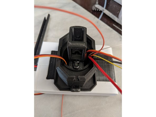
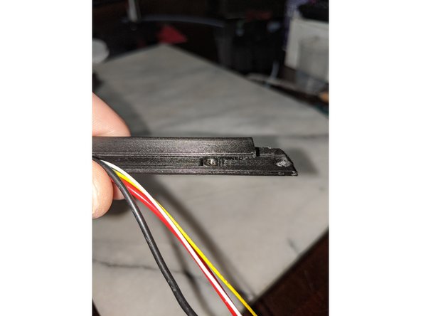
This step we will use a M3 Square Nut, the BarSkin print, and the TopBar print.
-
In pic 1 you can see there is a indent in the wire channel that will hold a M3 Square Nut. Place this nut flush down into the indent and insert the wires into the channel and that should hold it in place.
-
Slide the wires into the BarSkin print and then slide the BarSkin over the Headbar all the way up the HeadBar with the printed notch toward the top. Keep the wires in the channel of the HeadBar. When fully inserted, it will look like Pic 2.
-
Slide the TopBar print over the angle on the top of the HeadBar. This will go over the BarSkin and will be a somewhat tight fit to hold it all in place.
-
When done, you should have something that looks like Pic 3.
-
Just as a note, I printed the BarSkin in black and used a tiny bit of Rub N Buff silver on it to give it a worn metal look. I did the same with the TopBar print.
-
-
-
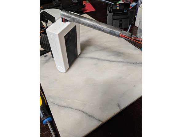
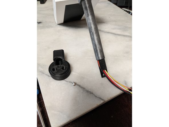
This will use the MainBarHolderA print and a M3 x 10mm long countersunk screw.
-
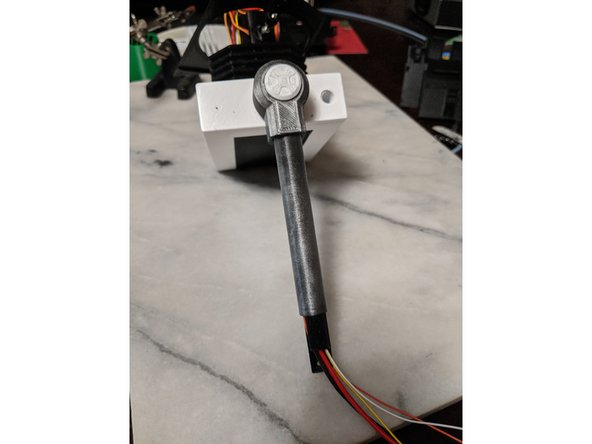
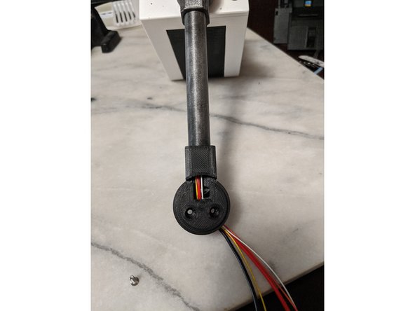
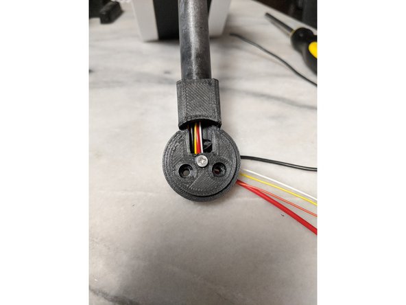
Feed the wires into the MainBarHolderA print and out the round hole on the back. Slide the MainBarHolderA onto the HeadBar all the way up and meet the BarSkin as seen in Pic 2. Look at the hole on the back and make sure the hole lines up witht he hole in the HeadBar.
-
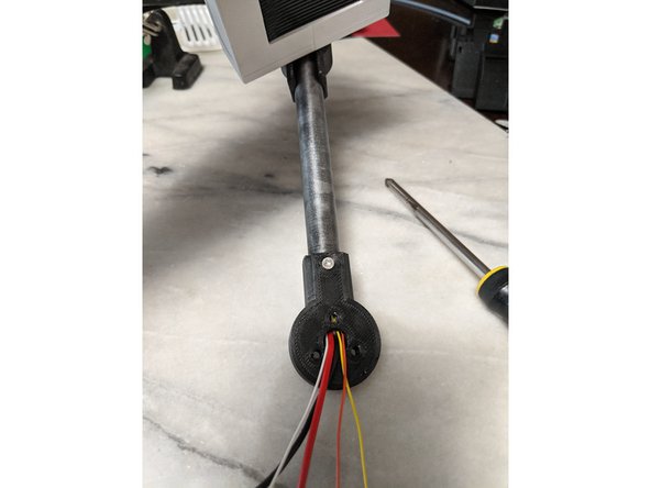
Secure the MainBarHolderA print with the 10mm long M3 screw to the HeadBar. Do not push on the screw and let it screw in smoothly so you do not push out the Square Nut that is sitting inside the HeadBar. Tighten the screw to secure as seen in Pic 3.
-
-
-
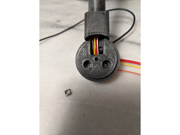
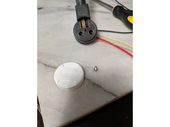
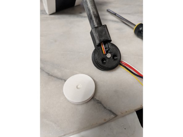
The screw hole in the center of the MainBarHolderA is covered for easier printing. Drill out the center hole so a M3 screw fits in there smoothly as seen in Pic 1.
-
Insert a M3 Square nut into the nut trap which is located near where the wires make the bend you see in Pic 1.
-
Now you will need a M3 x 8mm long screw and the MainBarCap
-
Fit the screw into the hole on the MainBarCap and make sure the head of the screw fully fits inside this hole. If it does not, use a razor blade or xacto to shave the edge of the hole until the screw head fits flush into the hole. Pic 3 shows the test fitting of the screw.
-
-
-
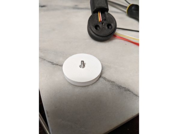
I used some sandpaper to rough up the head of the screw so epoxy will stick to it better as shown in Pic 1.
-
Screw the 8mm long M3 screw into the MainBarHolderA print until just barely tight. Do not over tighten this screw.
-
Mix up a small amount of 2 part epoxy and put a small drop into the center of the MainBarCap. Do not put too much epoxy in this print because we do not want any leaking out and locking everything into place. This is only to attach the cap to the screw.
-
-
-
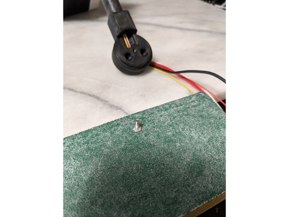
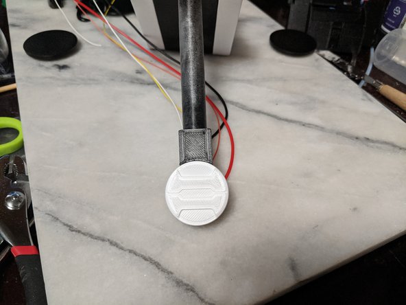
Push the MainBarCap in the orientation you want onto the screw so the epoxy covers the screw head.
-
Clamp the MainBarCap in place with something similar to Pic 2.
-
Allow the epoxy to fully cure (preferred 24 hours) so you know the bond holds. I tried to remove mine once too early and the epoxy broke free of the cap and I needed to swap out the screw and re-epoxy it and it stuck when I let it fully cure.
-
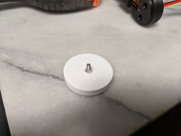
You can then use the MainBarCap to unscrew the screw from the MainBarHolderA and the screw will be epoxied to it as seen in Pic 3.
-
I added a small bit of extra epoxy to help hold the screw in place better since I now know the screw will attach with the cap in the orientation I want.
-
-
-
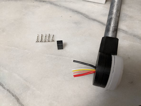
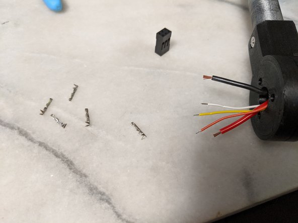
Time to attach plugs to the wires so the head is removable.
-
First trim the wires but leave enough length where you are comfortable with stripping the wires and crimping on them. How much I left is seen in Pic 1. We will also be using a 6 pin (2 rows of 3) female plug and 5 female crimps as seen in the pic.
-
Next separate the crimps from the row, and strip the ends of the wires.
-
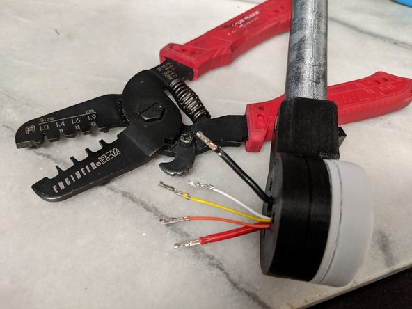
Crimp on the connectors. In pic 3 it shows the tool I use to do my crimping. It works very well. The PA-09 is the crimping tool I've been using for years for building 3d printers and crimping motor and endstop wires.
-
-
-
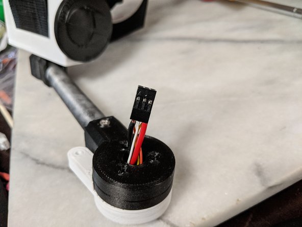
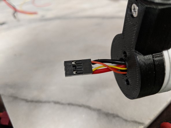
Pin 1 location is marked on the plug with a small arrow. The order of wires is up to you. For me, I used Pin 1 for the ground wire and the opposite on that row for the positive power to keep the power wires separate from each other. Then just put the servo wires in any order.
-


Cancel: I did not complete this guide.
2 other people completed this guide.