
Introduction
Support Michael Baddeley on his patreon page for files here: https://www.patreon.com/mrbaddeley/
If you wish to support the author of this guide, feel free to donate to me via paypal at http://paypal.me/guanu/
-
-
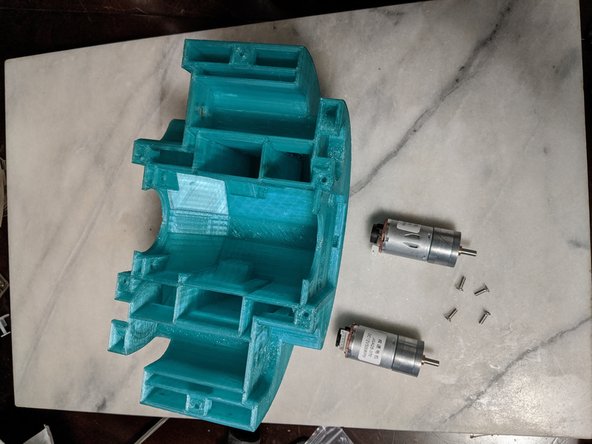
Printed Parts: MainFrame, FrontFrameInsert, RearFrameInsert, PololuGearA, PololuGearB, MainBar, MainServoGear
-
Screws: 8x M3 x 10mm long, 2x M4 x 10mm long, 2x M4 x 20mm long.
-
Square Nuts: M3 - Qty 19, M4 - Qty 4
-
6805 Bearings - Qty 2
-
Lead Shot
-
5 minute 2 part epoxy
-
Paper Towels
-
-
-
I just wanted to let you know that I made a big mistake when building this. I bought cheaper 20.4:1 12v motors from Amazon that looked to be very similar. They in fact are much weaker and I had all sorts of problems with them. Please purchase the actual Pololu brand High Power 20.4:1 motors. You do not need the ones with the encoder.
-
After purchasing the proper ones, disassembling the entire droid, and installing the proper motors, it functioned much better. Here are the proper motors: https://www.pololu.com/product/3203
-
The motor will come with tabs on the back for wires. Next to one of the tabs is a red dot. This is where I attached the red wires, and the wiring will be the same that is in the pics. I put the black wire on the other terminal of the motor.
-
-
-
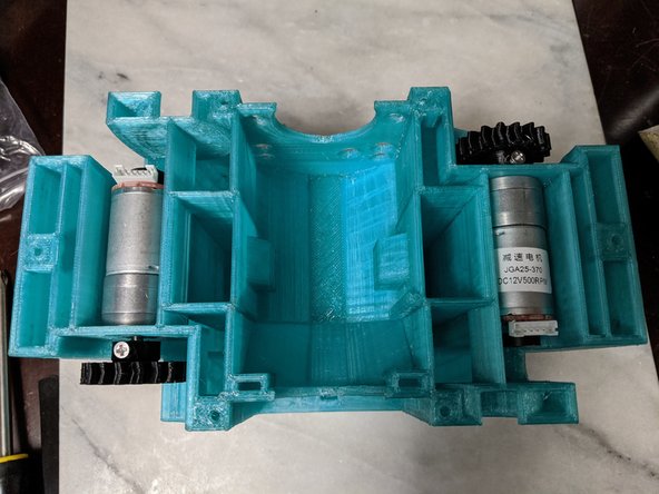
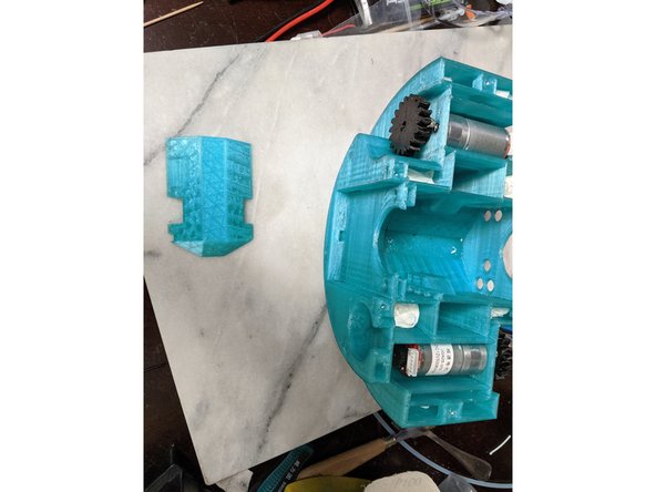
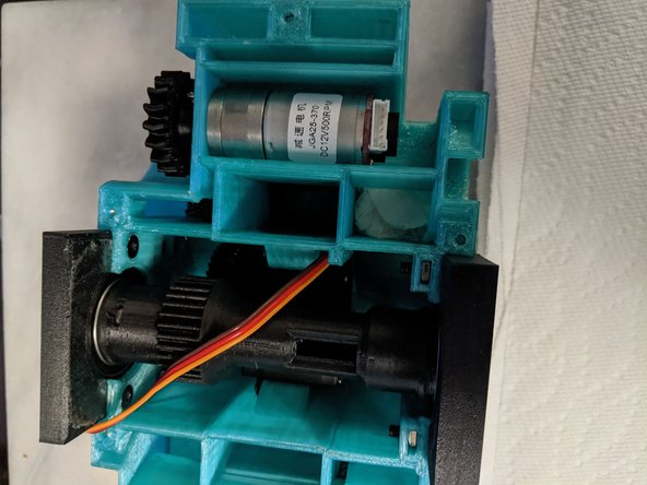
Here we will start with the MainFrame printed file and 2x 500 RPM 12v motors with encoders. The motors I used are Here Also you will need 4x M3 x 10mm long countersink screws.
-
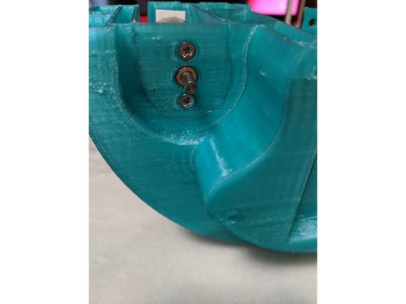
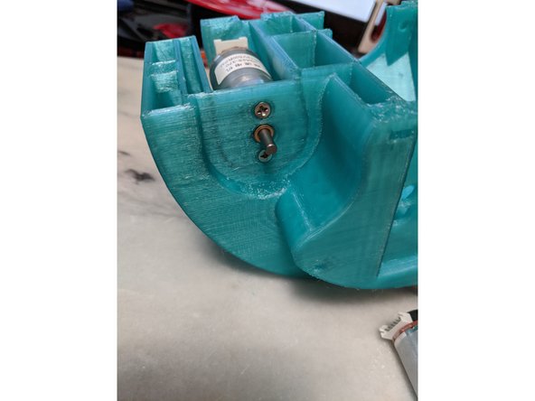
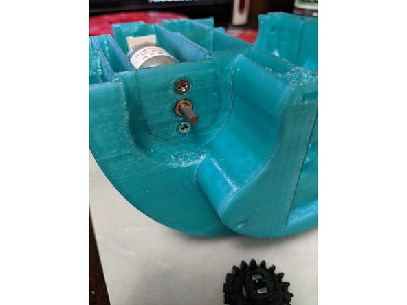
Using 2 M3 x 10mm long countersink screws per motor, attach the motors to the MainFrame as shown in Pic 2.
-
Repeat the process on the other side of MainFrame for the second motor as shown in Pic 3.
-
-
-
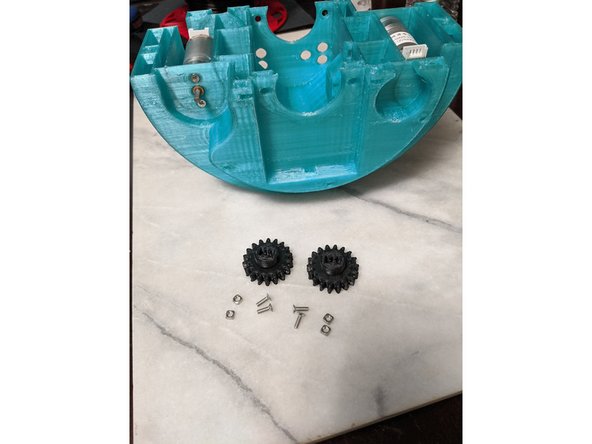
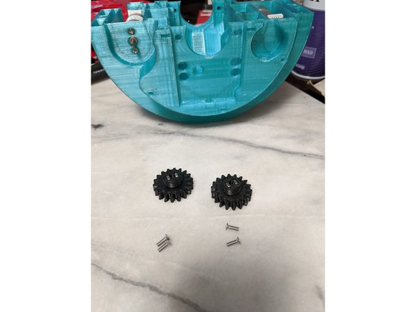
For the next two steps we will use the MainFrame assembly with drive motors attached, 4x M3 x 10mm long screws, and 4 M3 square nuts, and PololuGearA and PololuGearB.
-
First thing we will do is insert the square nuts into the PololuGear prints as shown in Pic 2.
-
-
-
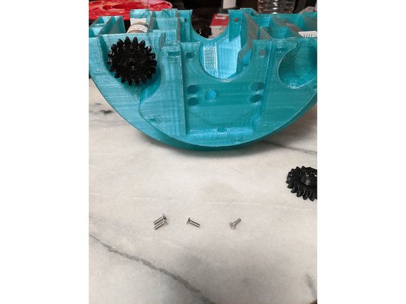
For both motors, align the flat of the motor shaft to the top so it is facing upward as shown in Pic 1.
-
Slide PololuGearA onto the first motor as shown in Pic 2. Pic 2 shows the "front" side which is also side A for the Lazy Susan files if you are keeping track.
-
Lining up the hole for the screw on the gear with the flat of the motor, attach the gear to the motor with the M3 x 10mm long screw making sure to screw onto the flat of the motor shaft.
-
Rotate the gear to the other side and attach the second screw to secure the gear to the motor shaft. Spin the gear to make sure it spins without wobble. If there is wobble, you can adjust the wobble by adjusting the screws attaching the gear to the motor shaft. Over tightening one screw can make the gear wobble.
-
Install the PololuGearB on to the rear side motor repeating the same steps to secure it into place.
-
You should now have both gears attached to the motors as shown in Pic 3.
-
-
-
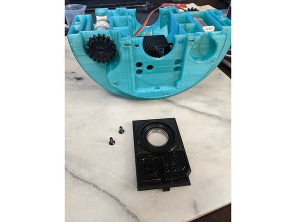
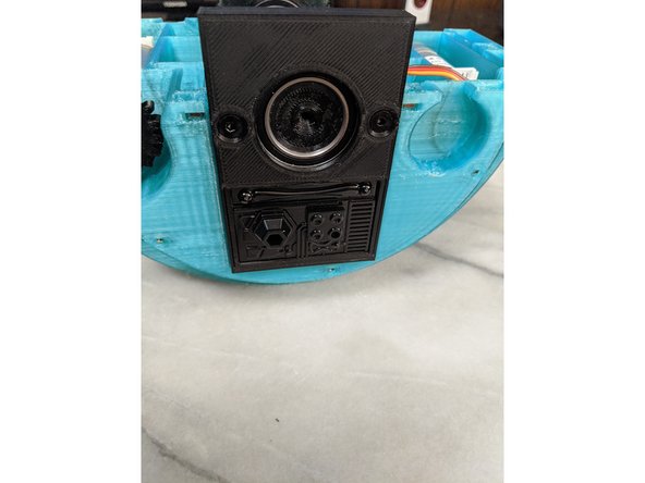
This step is fairly simple. Take the ServoBase print, and insert it into the center of the frame.
-
Make sure it is seated fully and flush with into the base of the frame.
-
-
-
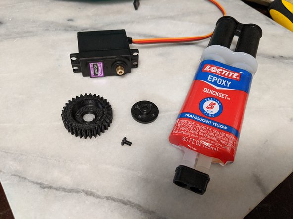
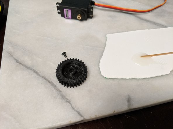
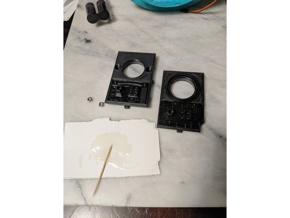
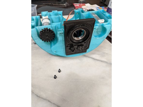
This step will use the MG996R Servo, MainServoGear printed part, the center screw for the servo, the round servo attachment, and 2 part epoxy.
-
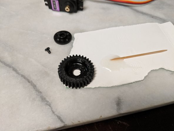
Mix up a very small amount of 2 part epoxy and spead it into the bottom center of the MainServoGear as shown in Pic 2.
-
Insert the servo gear attachment all the way into the MainServoGear to epoxy the attachment to the inside of the gear. I used a screwdriver to make sure the servo attachement was all the way inserted and flush inside the gear as shown in Pic 3.
-
Allow sufficient time for the epoxy to cure as when working on it and attaching it to the servo, you do not want the gear to be angled or not spin with a wobble.
-
Do not attach the gear to the servo yet. This will be done after installing in the frame which is next.
-
-
-
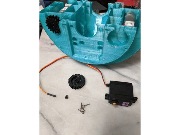
Here we will use the MainServoGear, the MG996R servo, the screws from the servo pack, and the MainFrame.
-
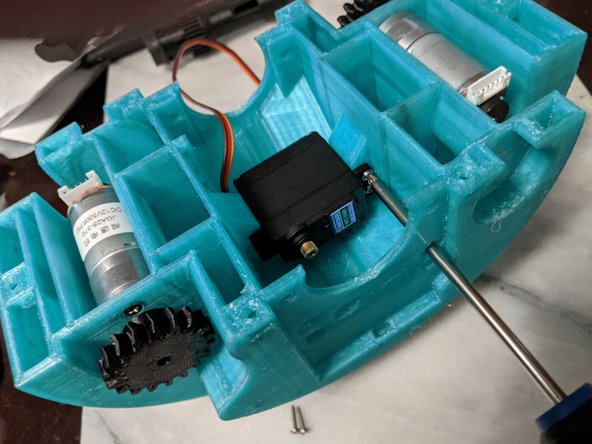
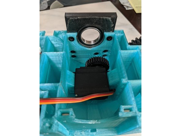
Insert the servo into the center of the MainFrame lining up the drive sprocket with the hole on the side of the MainFrame.
-
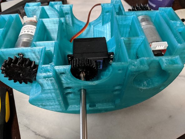
Attach the servo to the MainFrame using the servo screws as shown in Pic 2. The holes in the side of the MainFrame are for a screwdriver to go through to tighten the screws.
-
Press the MainServoGear with the epoxied on servo attachement onto the servo and screw it on securely with the screw as shown in Pic 3.
-
-
-
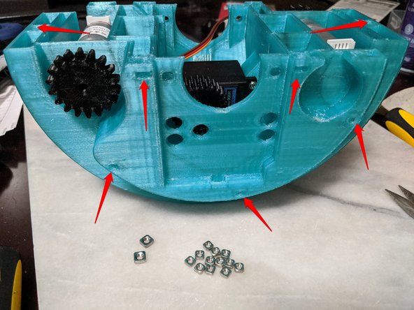
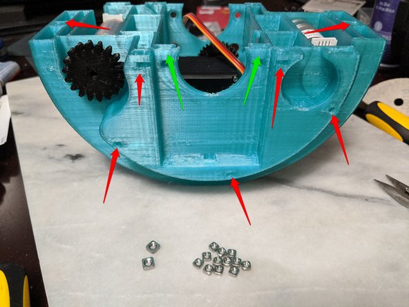
Here you will use 12x M3 Square Nuts and 2x M4 Square Nuts for setting up the main frame.
-
Refer to the pictures on where to insert the square nuts. All arrows in RED are M3 square nuts. All arrows in GREEN are M4 square nuts.
-
Insert the nuts fully into the openings until the threads align with the holes for the screws.
-
As before, the nuts will most likely press fit and hold in place. If they do not, use a small drop of hot glue to hold them in place.
-
-
-
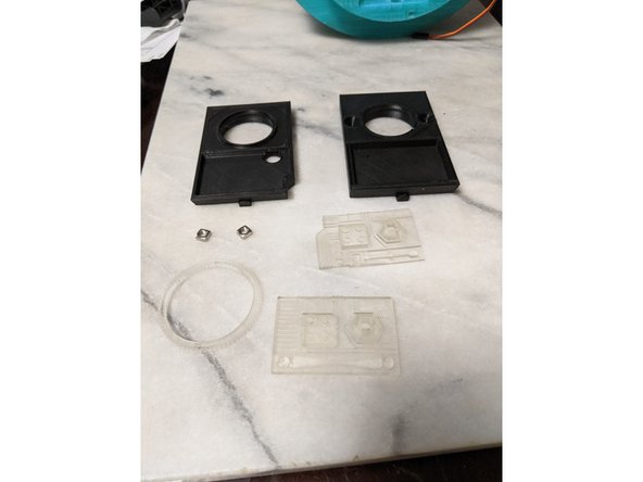
If you decided to print the Resin version of the Frame Inserts, this will be covered in this step. If you used the full print file, skip to the next step.
-
You will use 2 M4 Square Nuts, Front and Rear Frame Insert prints, and the Resin Frame Inserts long with the Ring as shown in Pic 1.
-
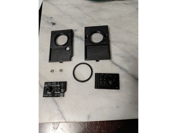
If you did not use Black resin as I did not, you will first need to paint the resin parts Black.
-
Once the paint has fully dried, mix up some 2 part epoxy or use super glue to glue them in place as shown in Pic 3.
-
-
-
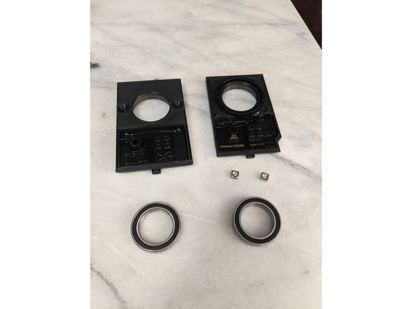
Here you will use FrontFrameInsert and RearFrameInsert prints or the insert assemblies made in the previous step. You will also use 2x M4 Square Nuts and 2x 6805 Bearings as shown in Pic 1.
-
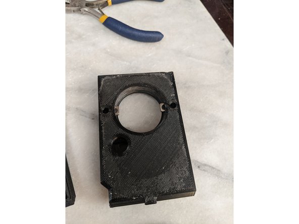
FrontFrameInsert has 2 pockets for the M4 Square Nuts. Insert the Square Nuts into the pockets as shown in Pic 2. Insert the nuts fully until the threads align with the holes.
-
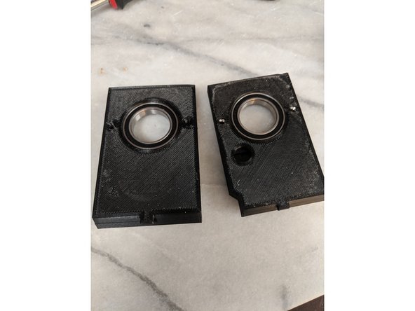
Next you will insert the 6805 bearings into the frame inserts.
-
I sanded out the hole these bearings go into with a light sanding on my dremel to get them to fit snugly. Make sure they insert all the way. There is a small lip on the prints to stop the bearings. Your assemblies will now look like Pic 3.
-
-
-
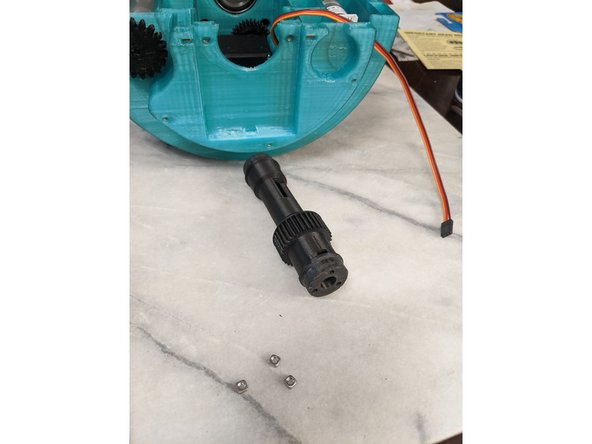
Here you will need the MainBar print, 3x M3 Square Nuts, and a 1/8 inch drill bit.
-
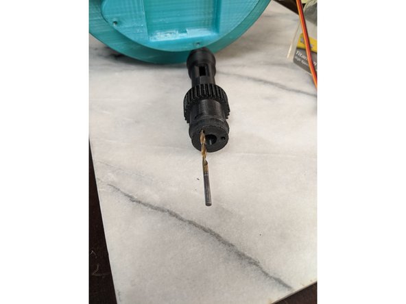
The first thing you want to do is drill the 3 holes out as shown in Pic 2 using a 1/8 inch drill bit. The holes are capped for easier printing and making the nut traps cleaner, so they must be drilled out.
-
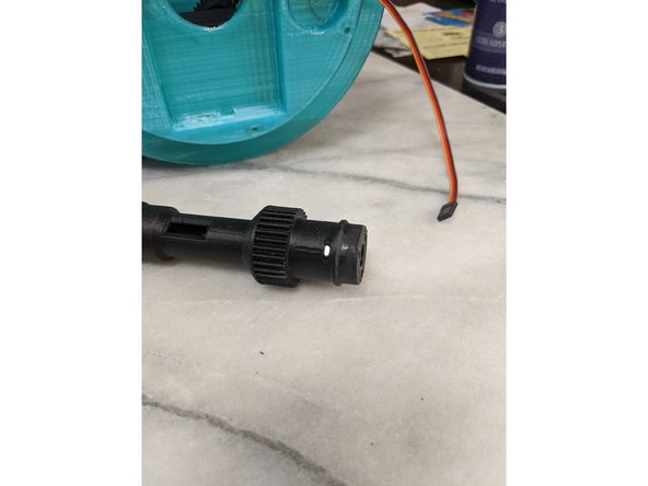
Drill out all 3 holes and when done, you will use the 3x M3 Square Nuts to insert into the nut traps as shown in Pic 3.
-
-
-
Here you will use the FrontInsert print and 2 M4 x 10mm long countersunk screws. 8mm long screws will work as well if you do not have 10mm, but I used 10mm just fine as that is what I had.
-
Insert the FrontInsert into the frame and click it down engaging the tab on the bottom of the FrameInsert into the MainFrame and clicking it down fully as shown in Pic 2.
-
From the inside of the frame and the rear of the FrontFrameInsert, insert the screws into the two holes and secure the insert into the frame as shown in Pic 3.
-
-
-
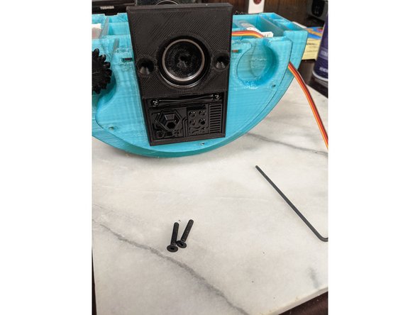
For this step we will use the MainBar print, RearFrameInsert print, and 2x M4 x 20mm long countersunk screws. I used 22mm long screws as it is all I had and since the frame has room for them, it worked fine. I believe you can use anything from 18mm - 24mm long without issue.
-
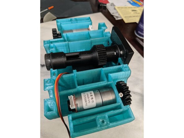
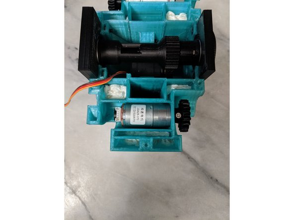
Insert the MainBar print into the bearing in the FrontFrameInsert as shown in Pic 2. I personally lightly sanded the end of the MainBar print to fit snug into the bearing as initially it would not insert. You can see this in Pic 1 on the exposed end of the MainBar.
-
Make sure that the gear on the MainBar is engaged with the gear on the Servo in the frame. They should mesh.
-
Using the RearFrameInsert, insert the end of the MainBar into the bearing of that insert and insert the RearFrameInsert into the frame. Also make sure the tab of the insert gets fully inserted into the frame and it is seated down fully.
-
Use the M4 screws to attach the insert to the frame as shown in Pic 3.
-
-
-
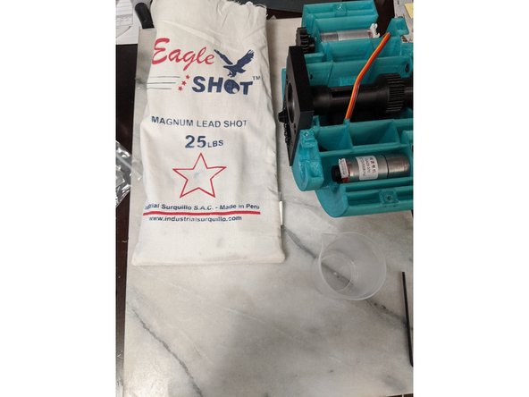
Here we will add the lead shot for ballast to keep everything stable. I purchased a bag of lead shot from my local Cabelas outdoors store. This is a large bag I purchased for other droids as well, and had lead left over. You can purchase lead shot from hunting departments of sports stores or Amazon.
-
Michael used 2kg of lead shot, and I had 5 pounds left so we used about the same amount which will be shown here.
-
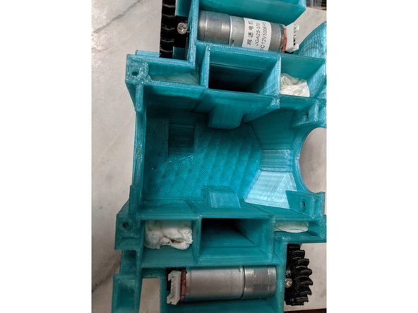
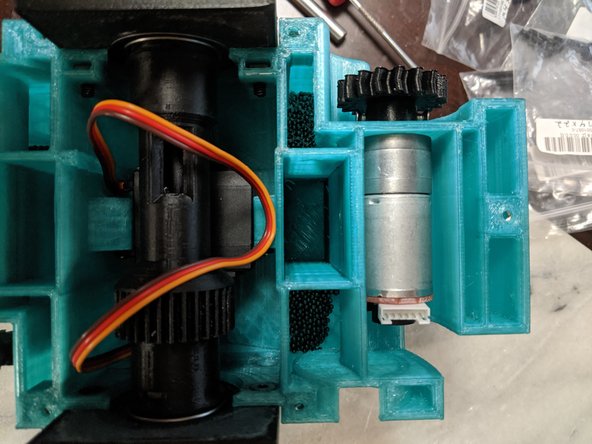
Fill the lead shot in any of the holes that lead to the center cavity of the Frame. You can see the lead shot in Pic 2, and this is the hole I filled at. I used the holes on both sides to try to even it out as much as possible.
-
When you have about 5 pounds of lead shot in the base, make sure to shake it around and back and forth to evenly distribute the weight as much as possible.
-
-
-
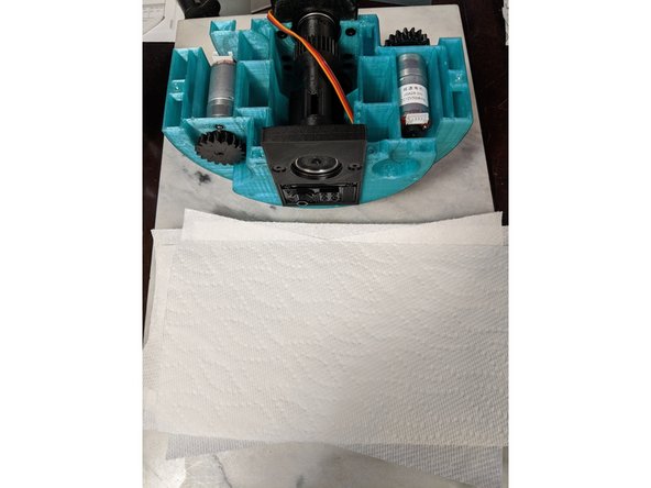
I talked to Michael about how to secure the ballast in place since the cavity is so large it cannot be secured in place with epoxy as it would take far too much epoxy to fill and he said he used foam or bubble wrap to fill the cavity which also makes it still removable. I went the cheap and what I had available route and used paper towels.
-
You can see in Pic 1 the paper towel I used. I ended up using 2 sheets of paper for each opening except the thin slit opening near the end which I added one sheet. This ended at a total of 18 sheets of paper towel.
-
Fold up the paper or foam and start filling the cavities to fill out the open areas to secure the ballast in place. The first paper towel I shoved in can be seen in Pic 2.
-
Pic 3 shows my final fill of towel to secure the ballast. All larger openings got 2 paper towels in them, and as said above after all the larger holes were filled I added one more to the thin longer slit towards the edge as well to secure everything in place. There are 8 larger openings and 2 thin slits in total that need to be blocked off.
-
Cancel: I did not complete this guide.
3 other people completed this guide.