
Introduction
THIS GUIDE IS IN-PROGRESS AND NOT COMPLETE YET!
Support Michael Baddeley on his patreon page for files here: https://www.patreon.com/mrbaddeley/
If you wish to support the author of this guide, feel free to donate to me via paypal at http://paypal.me/guanu/
-
-
To assemble both lazy susan sides you will need the following:
-
M3 Square Nuts - Qty 16
-
Countersink M3 x 10mm long Screws - Qty 12 ; Countersink M3 x 8mm long screws - Qty 16
-
683ZZ Bearings - Qty 12
-
10mm Plastic Ball Bearings - Qty 116 The ones I used are located Here
-
*** EDIT: After test fitting the 10mm bearings, they were too tight on my assembly and I ended up using 3/8 inch delrin bearings- Qty 124
-
Printed parts: DriveEdgeA, DriveEdgeB, InnerSusanA, InnerSusanB, OuterRingA, OuterRingB, OuterSusanA, OuterSusanB, SusanPlugA, SusanPlugB.
-
-
-
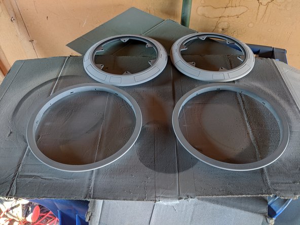
You will be matching OuterRingA and OuterSusanA together
-
Along with matching OuterRingB and OuterSusanB
-
Test fit them together to make sure they connect together flush and there are no printing issues or areas that need to be sanded or trimmed so they fit together well.
-
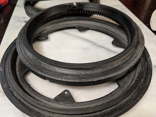
Mix up some 2 part epoxy and spread it on the inside of OuterRingA and OuterRingB and coat the inside as shown in Pic 2.
-
Snap the pieces together and place something heavy and flat on it while it sets to hold it flat. I used a marble cutting board to weigh the pieces on the table while the epoxy cured.
-
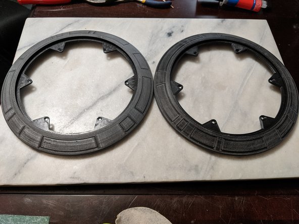
Once dry, you will have the outer ring epoxied together and look like Pic 3.
-
-
-
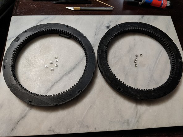
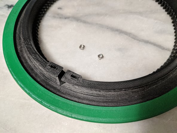
This step will use the InnerSusanA and InnerSusanB prints along with 12 M3 square nuts as shown in Pic 1.
-
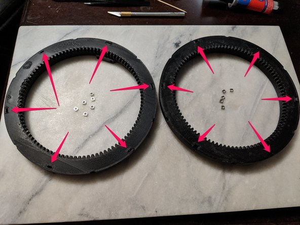
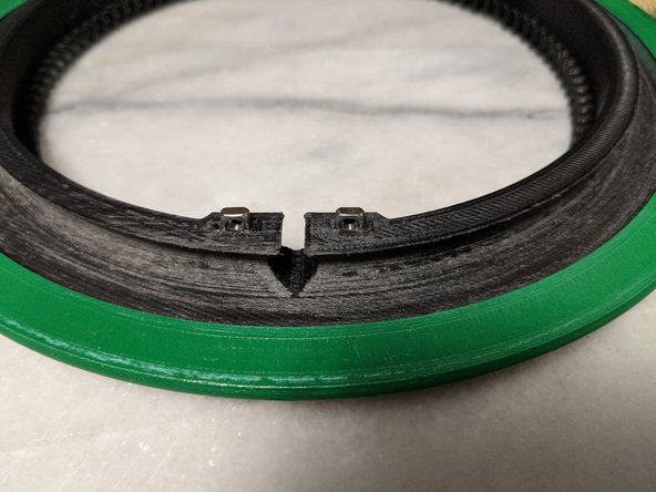
The nuts are inserted into the slots pointed out as shown in Pic 2.
-
If it is a tight fit, tap them in with a flat blade screwdriver until the threads are lined up with the hole from the outer edge. If the nuts are loose in the slot, hold them in place with a small dot of hot glue.
-
-
-
Before finishing the assembly, now is the time to go over the parts and do any sanding and painting that will be done to the parts.
-
The most important place to check for required sanding is the raceways for the ball bearings. The InnerSusan and OuterSusan prints. Make sure the curved areas the ball bearins are going to be in is smooth. If there is any z seam or bumps, be sure to sand them smooth for best results.
-
I sanded down the entire channel for the bearings on my print. Just because no printed part will be perfect and wanted to give more room for the ball bearings which will be much more accurate than a printed part. This also will help knock down layer lines and any printing imperfections.
-
Now is also the time to sand down the OuterRing prints and DriveEdge prints to prep for painting if you plan on painting them. How much you sand is up to you and how detailed and smooth you want your parts to be. I just gave mine a rough sanding as to remove any print marks but not going for a super smooth finish for this manual.
-
-
-
Now is time to paint the DriveEdge prints and OuterRing prints if you are going to paint your parts.
-
This is done now because while they are seperate the DriveEdge is green and the OuterRing is white.
-
Note that my painting is not official and I am not a professional droid builder or painter, so for the guide I'm just giving suggestions. Do the painting as you desire.
-
For my painting I used Rustoleum Filler Primer to help somewhat hide layer lines. Pic 1 shows the parts primered. I am personally not sanding it super smooth because I like to show off that the droid is printed and prefer to see some layer lines.
-
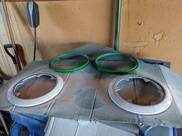
The DriveEdge I printed with Rustoleum 2x Meadow Green and the OuterRing I printed with Rustoleum 2x Gloss White. Shown in Pic 2.
-
My paint job will not be that great as living in the midwest it is the middle of winter and extremely cold which is not idal for painting in the garage.
-
-
-
If you painted the parts, make sure you wait until the paint is fully dry before moving on since you will be handling the painted parts.
-
Parts used in this step:
-
DriveEdgeA and DriveEdgeB
-
InnerSusanA and InnerSusanB
-
M3 x 12mm countersunk screws - Qty. 12 (6 per lazy susan)
-
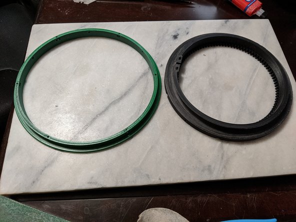
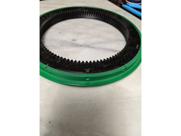
For this part you will be using the DriveEdge (painted green) and the InnerSusan prints. The InnerSusan print is the large gear print as seen in Pic 1.
-
With the gear side of InnerSusan down on the table side, Place DriveEdge with the protruding edge up over InnerSusan, lining up the round countersunk screw holes with the square nuts inserted into the InnerSusan as shown in Pic 2.
-
Insert a M3 x 12mm long countersunk screw into each of the round recesses of the DriveEdge prints screwing it into the square nut inserted into the InnerSusan as shown in Pic 3. Repeat this for all 12 screws (6 per lazy susan)
-
-
-
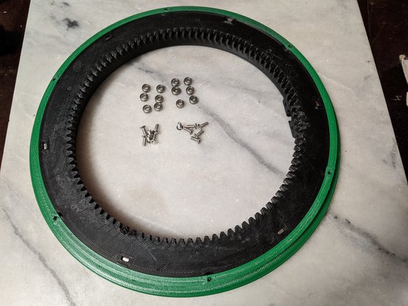
This step will use 12 683ZZ Bearings and 12 M3 x 8mm long countersunk screws as shown in Pic 1.
-
Insert the bearing into the slots on the side of the DriveEdge making sure they are in there somewhat loosely. I used a dremel with a small router bit to clear out the opening to get them to fit looser. Reference Pic 2.
-
Screw the M3 screw into the DriveEdge and through the 683 bearing as shown in Pic 3.
-
Repeat this process for all 6 locations on each DriveEdge for a total of 12 locations.
-
-
-
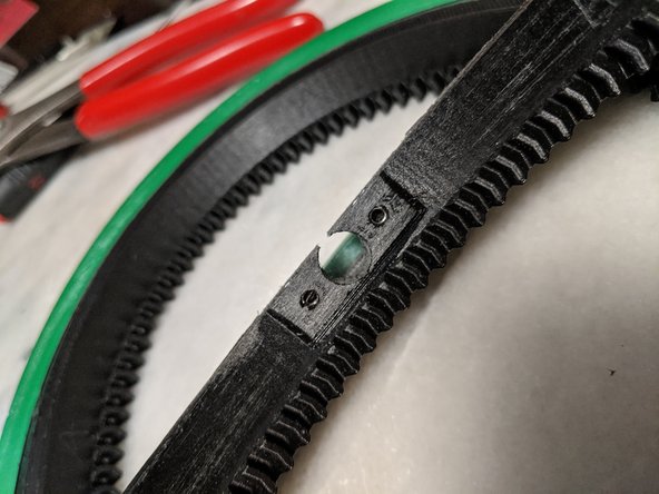
Here you will use 4 M3 square nuts for the InnerSusan. You will use 2 nuts per InnerSusan.
-
Insert the square nuts into the InnerSusan prints as shown in Pic 2.
-
Tap the nuts down until the threads line up with the holes on the InnerSusan print. If the nuts do not need tapping in and are loose, hold them in place with a small dab of hot glue.
-
When aligned they will look like Pic 3.
-
-
-
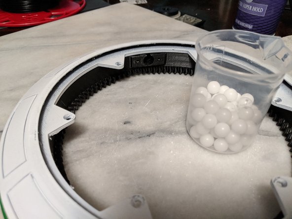
Here is where there is some option. Michael Baddeley designed the lazy susan for 116 10mm plastic bearings (58 per side). I ordered them and found them to be too tight in the lazy susan upon assembling. So I ordered 200 3/8 inch delrin bearings which are 9.5mm and fit much better for my prints so that is what I used.
-
You will use the DriveEdge assembly used in the previous step, along with the OuterRing/OuterEdge assembly that was glued together earlier. Along with the printed parts you will use the ball bearings mentioned above. If using 3/8 inch bearings, you will use 62 bearings in each side for a total of 124 bearings.
-
Set the OuterRing assembly on top of the DriveEdge assembly as shown in Pic 2.
-
-
-
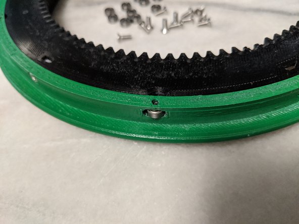
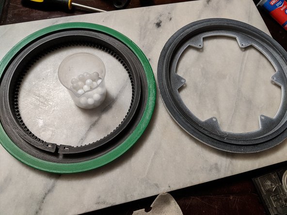
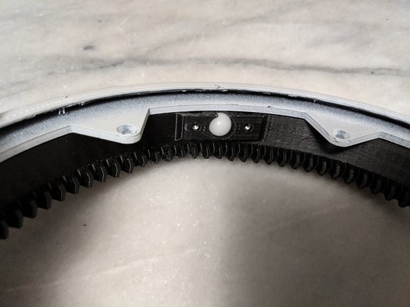
With 62 bearings (or 58 if using 10mm), you will be inserting them into the hole of the InnerSusan as shown in Pic 1.
-
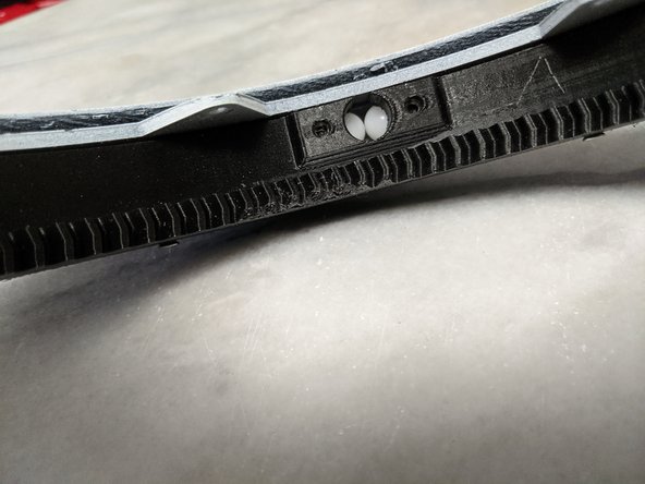
Feed in all the bearings one at a time and push them in using the next bearing to push the previous one in until they all fit in as shown in Pic 2.
-
The final bearing will be sticking out like Pic 2, and you can use a screwdriver or pretty much anything to get it all the way into the channel.
-
With all bearings installed, your assembly should look like Pic 3.
-
-
-
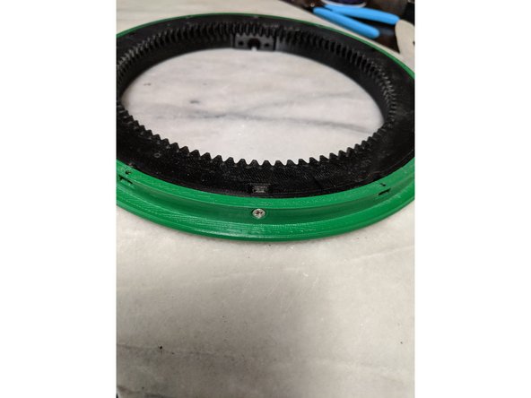
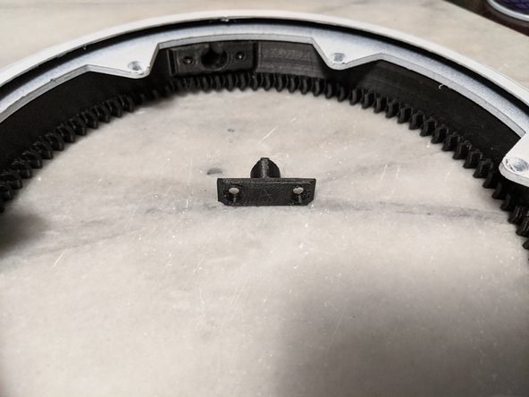
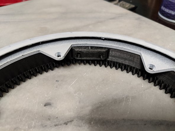
This step will use the SusanPlugA and SusanPlugB files to hold the ball bearings inside the lazy susan.
-
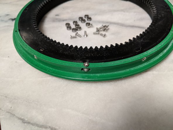
Insert the plug into the hole you inserted the bearings into as shown in Pic 2.
-
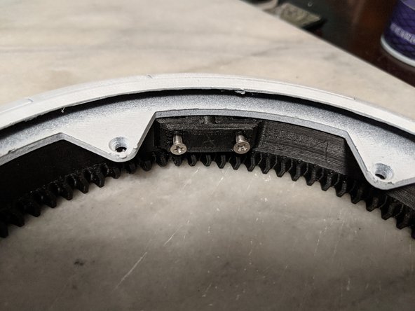
Using M3 x 8mm countersunk screws attach the SusanPlugs to the InnerSusan as shown in Pic 3.
-
-
-
Congratulations, you have assembled the Lazy Susan portion of the D-O build. You should now have 2 Lazy Susan assemblies complete.
-


Cancel: I did not complete this guide.
4 other people completed this guide.